Connector for electrical equipment

A technology for power equipment and connectors, which is applied in the field of connectors for power equipment, can solve the problems of inconsistency between cables and connectors, easily damaged connectors, and easily damaged cables, etc., and achieve the effects of improving the use range, uniform supporting force, and preventing the insulation layer from breaking

Active Publication Date: 2021-10-01
GUANGDONG POWER GRID CO LTD +1
View PDF8 Cites 0 Cited by
  • Summary
  • Abstract
  • Description
  • Claims
  • Application Information

AI Technical Summary

Problems solved by technology

[0006] For this reason, the embodiment of the present invention provides a connector for electric equipment to solve the problems in the prior art that the local area of ​​the cable close to the connector is bent and easily damaged, and the size of the cable and the connector does not match and the connector is easily damaged.

Method used


Image

  • Connector for electrical equipment
  • Connector for electrical equipment
  • Connector for electrical equipment

Examples


Embodiment Construction

[0035] The implementation mode of the present invention is illustrated by specific specific examples below, and those who are familiar with this technology can easily understand other advantages and effects of the present invention from the contents disclosed in this description. Obviously, the described embodiments are a part of the present invention. , but not all examples. Based on the embodiments of the present invention, all other embodiments obtained by persons of ordinary skill in the art without making creative efforts belong to the protection scope of the present invention.

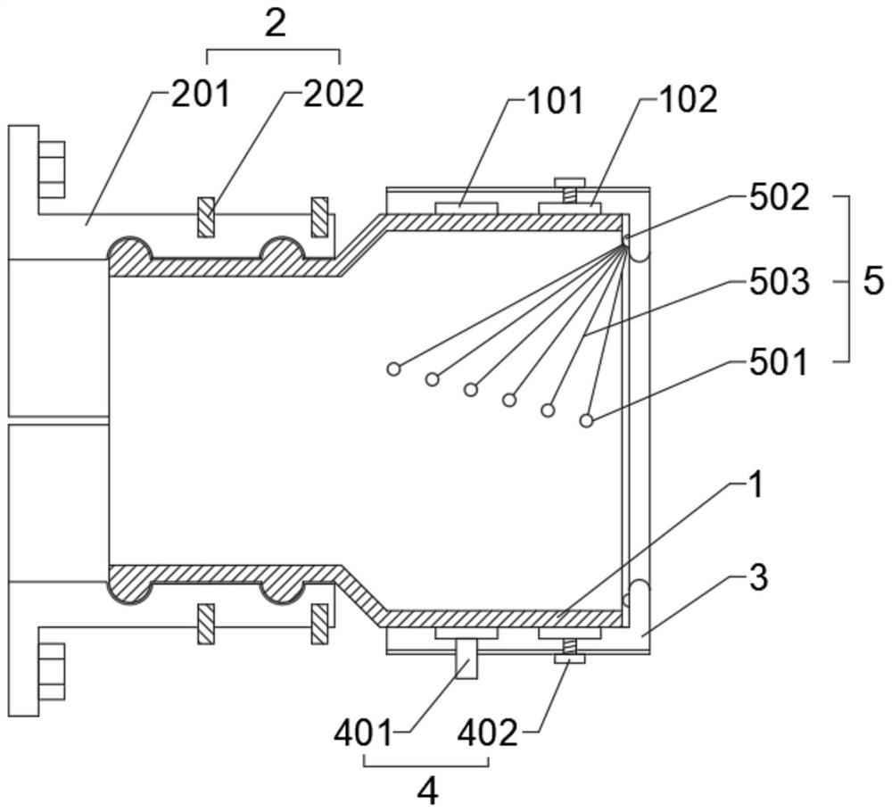
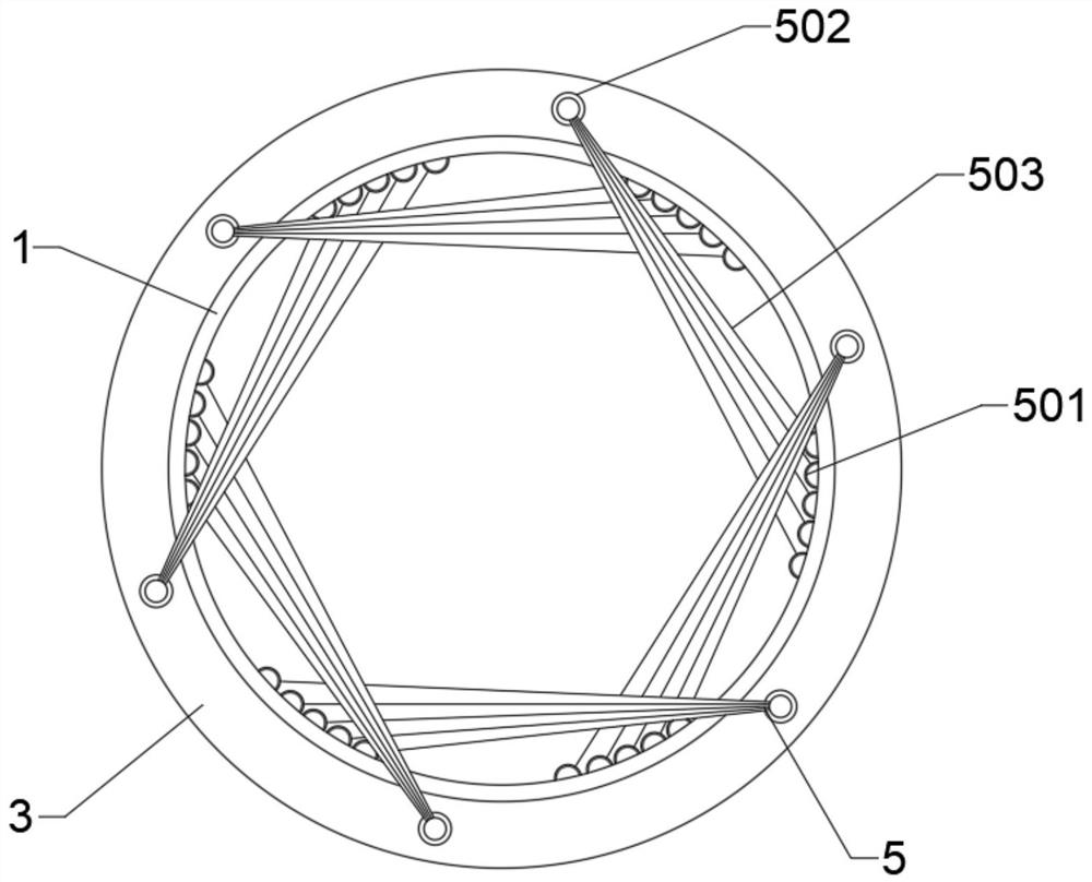
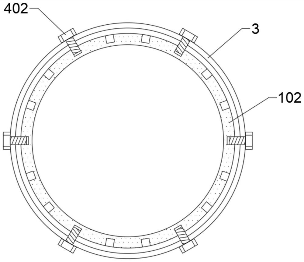
[0036] like figure 1 and figure 2 As shown, the present invention provides a joint for power equipment, which specifically includes an insulating installation cylinder 1 for cables to pass through. A detachable fixed mounting seat 2 is provided behind the insulation installation cylinder 1, and the insulation installation cylinder 1 is fixedly installed Seat 2 is installed at the equipment cab...


PUM


Abstract

The embodiment of the present invention discloses a joint for electric equipment, which includes an insulating installation cylinder for cables to pass through, and an elastic outer cylinder that rotates around the insulation installation cylinder is provided on the outside of the insulation installation cylinder, and the insulation installation cylinder There are multiple sets of rope-supporting mechanisms distributed equidistantly inside, and one end of multiple sets of rope-supporting mechanisms is connected to the corresponding node at the front end of the elastic outer cylinder, and multiple sets of rope-supporting mechanisms inside the insulating installation cylinder The mechanism cooperates with the elastic outer cylinder to form a cross wire ring structure for flexible supporting cables. The insulation installation cylinder is set at the cable interface of the power equipment for the cable to pass through, and the cross wire ring for supporting the cable is set in the insulation installation cylinder The structure can reduce the transverse stress generated at the interface between the cable and the power equipment, change the large local bending of the cable into a small bending in a larger area, and prevent the insulation layer from being broken due to excessive local bending of the cable.

Description

technical field [0001] Embodiments of the present invention relate to the technical field of cable joints, in particular to a joint for electric equipment. Background technique [0002] The cable joint is a device used to lock and fix the incoming and outgoing lines. It mainly plays the role of waterproof, dustproof and shockproof, and prevents rainwater from entering the box from the through hole to cause safety hazards in rainy weather. [0003] At present, the common cable joints on the market are lock nut joints. The lock nut is installed on the cable interface opened by the power equipment in advance, and the installation is realized by passing the cable into the lock nut and tightening the lock nut. Still there are following deficiencies in the prior art: [0004] (1) The contact between the connector and the cable is rigidly supported. When the entrance direction of the cable and the connector is greatly different, a large bending range will be generated in the local...

Claims


Application Information

Patent Timeline
Patent Type & Authority Patents(China)
IPC IPC(8): H02G15/04
CPCH02G15/046
Inventor 牛世俊黄庆全许儒仰陈毅润
Owner GUANGDONG POWER GRID CO LTD
Why Eureka
Try Eureka