Strip Cooling Spray Header and Its Installation Structure Between Rolling Mill Stands

A technology for steel strip cooling and rolling mill stand, which is applied in the direction of workpiece cooling device, metal rolling, metal rolling, etc., and can solve the problem of inability to adjust the distance between the nozzle and the injection point, the temperature control effect of the strip body is not obvious, and the impact force of the adjustment mechanism Large and other problems, to achieve the effect of reducing temperature inhomogeneity, avoiding excessive temperature drop, and improving temperature uniformity

Active Publication Date: 2019-12-31
武汉钢铁有限公司
View PDF2 Cites 0 Cited by
  • Summary
  • Abstract
  • Description
  • Claims
  • Application Information

AI Technical Summary

Problems solved by technology

[0003] Chinese patent ZL201310311026.3 uses cooling water headers and baffle plates to control the cooling speed of the steel belt, but it is only for the control of the belt head and tail, and the temperature control effect on the belt body is not obvious
Chinese patent ZL201521074176.8 uses an adjustable nozzle to adjust the spray angle, thereby controlling the cooling speed of the steel strip in the transverse direction. Its shortcoming is that this patent uses a straight spray header, and the distance between the nozzle and the spray point cannot be adjusted. , the injection pressure cannot be adjusted, and at the moment of injection start and stop, the adjustment mechanism receives a huge impact force, and the equipment failure rate increases significantly

Method used


Image

  • Strip Cooling Spray Header and Its Installation Structure Between Rolling Mill Stands
  • Strip Cooling Spray Header and Its Installation Structure Between Rolling Mill Stands
  • Strip Cooling Spray Header and Its Installation Structure Between Rolling Mill Stands

Examples


Embodiment Construction

[0025] The present invention will be further described in detail below in conjunction with the drawings and specific embodiments.

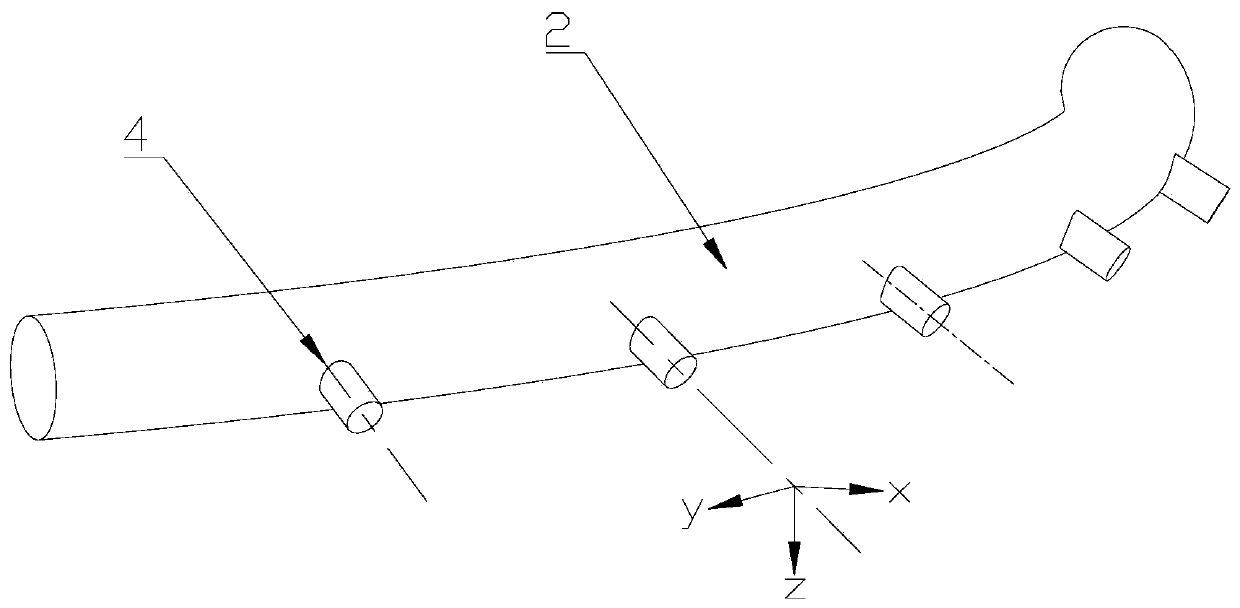
[0026] Such as Figure 1~3 As shown, the cooling spray header for the steel strip between the rolling mill stands designed by the present invention includes a manifold 2 and multiple nozzle tubes 4, among which:

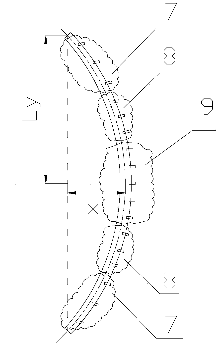
[0027] The shape of the manifold 2 is represented by the central axis of the pipe as an axisymmetric curve intercepted from a conic section, and the length L of the manifold 2 along its axis of symmetry x And its opening width L y Ratio L x / L y =0.05~0.25.

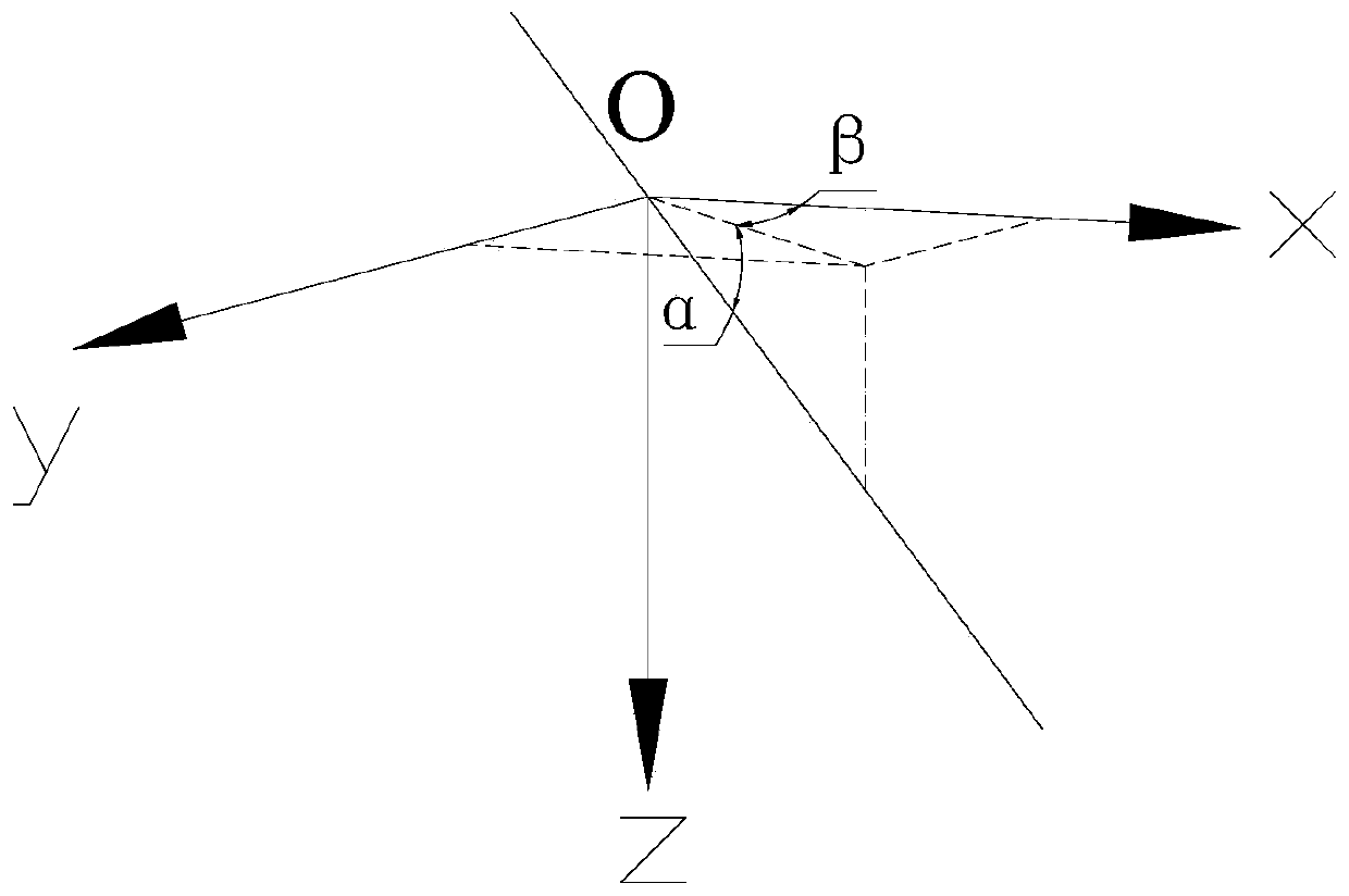
[0028] A plurality of nozzle tubes 4 are arranged along the protruding side of the manifold 2, and are inclined to one side of the plane where the central axis of the manifold 2 is located, so that the central axis of the nozzle at the outlet of the nozzle 4 is the same as the central axis of the manifold 2 The angle between the planes is α=15°~60°.

[0029] The manifold 2 is divided into ...


PUM

PropertyMeasurementUnit
angleaaaaaaaaaa

Abstract

The invention discloses a cooling and spraying header for steel strips between rolling mill frames and a mounting structure thereof. The cooling and spraying header comprises a collecting pipe and multiple nozzle pipes; the collecting pipe is a section of axial symmetry curve represented by the central axis thereof and cut from a conical curve; the ratio of the length of the collecting pipe alongthe symmetric axis to the opening width is 0.05-0.25; and the multiple nozzle pipes are arranged along the projected side of the collecting pipe, and are inclined to one side of the plane of the central axis of the collecting pipe, so that an included angle alpha between the central axis in outlets of the nozzle pipes and the plane of the central axis of the collecting pipe is 15-60 degrees. During mounting, two sets of cooling and spraying headers are adopted, and are mounted at the upper parts and the lower parts of the steel strips; and the symmetric axes of the cooling and spraying headersand the middle lines of steel plates are on the same vertical surface. The problems of nonuniform distribution of the transverse temperature of the steel strips and quicker edge temperature drop canbe solved.

Description

Technical field [0001] The invention relates to a steel belt cooling device, in particular to a steel belt cooling spray header between rolling mill stands and an installation structure thereof. Background technique [0002] The final rolling temperature control accuracy of hot strip is a key indicator of the performance of the strip. In order to ensure the final rolling temperature, higher requirements are placed on the cooling water system between the stands. The cooling water system between the hot strip mill stands not only improves the surface quality of the steel strip, but also prevents secondary scale formation. However, during the cooling process of the steel strip, due to the faster edge cooling, the transverse temperature of the steel strip will be inconsistent, resulting in edge waves after the steel strip is cooled. This phenomenon is especially obvious when rolling thin steel strips. For this reason, it is necessary to reduce the temperature drop at the edge of th...

Claims


Application Information

Patent Timeline
Patent Type & Authority Patents(China)
IPC IPC(8): B21B45/02B21B37/76
CPCB21B37/76B21B45/0218B21B45/0233
Inventor 邱碧涛董元广胡超陈燕才熊雯张堂正张雪荣李欣高广洪
Owner 武汉钢铁有限公司
Why Eureka
Try Eureka