Anchoring device for railway rail fastening assembly

An anchoring device, railway track technology, applied in the direction of track, rail holder, road, etc., can solve problems such as increased manufacturing cost, inability to remove anchoring device, complexity, etc.

Active Publication Date: 2021-01-29
PANDROL LTD
View PDF10 Cites 0 Cited by
  • Summary
  • Abstract
  • Description
  • Claims
  • Application Information

AI Technical Summary

Problems solved by technology

However, such anchors are difficult to cast due to the complexity of their features
In particular, the pattern of anchoring means 12 cannot be removed from the mold without the walls of the void at least partially collapsing.
As a result, the anchor device 12 requires extensive machining after casting, thereby increasing manufacturing costs

Method used


Image

  • Anchoring device for railway rail fastening assembly
  • Anchoring device for railway rail fastening assembly
  • Anchoring device for railway rail fastening assembly

Examples


Embodiment Construction

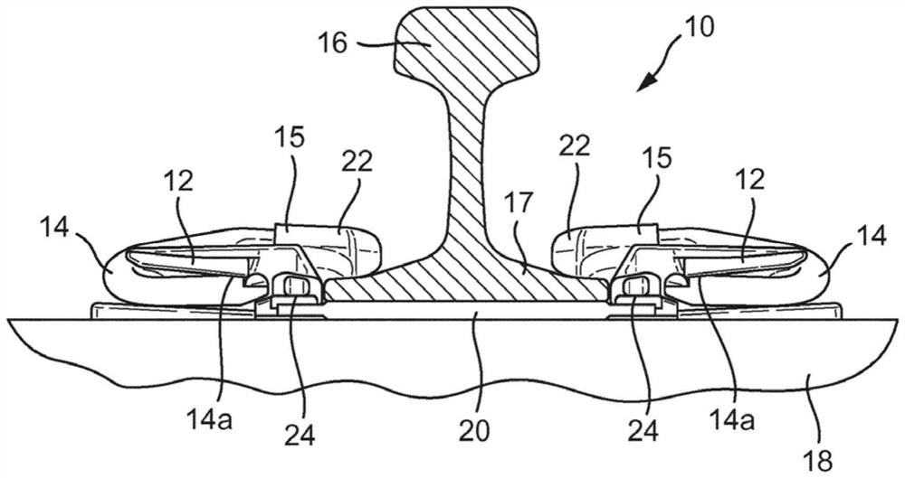
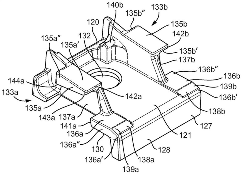
[0044] Referring to FIG. 2, an anchoring device 120 according to a first arrangement of the present application, such as a shoulder, may be formed as Figure 1a A portion of a railway track fastening assembly 10 is depicted. In other words, anchoring device 120 can replace Figure 1a Anchoring device 12 depicted in . As such, the anchor 120 is configured to receive a railroad track fastening fastener 14 and may be connected to an underlying subgrade 18, such as a railroad tie or slab. Corresponding anchoring devices 120 are provided on both sides of the railroad track 16 for holding the fastener 14 pressed on the rail foot 17 . Fastener 14 secures railroad track 16 to the subgrade below by the force exerted by the fastener on anchor 12 and track 16 .

[0045] The clasp 14 has first and second legs 14a and a rail "toe" 15 between the first and second legs 14a. The fastener 14 may be M-shaped, for example when viewed from above and when installed. The catch 14 may be configur...


PUM


Abstract

An anchoring device (120) for use in retaining a railway rail fastening clip having first and second leg portions and a rail-bearing portion therebetween, the anchoring device comprising: a base member (121); an opening (132) in the base member (121) configured to receive a fastening component for fastening the anchoring device to an underlying foundation; and first and second clip-retaining sides(133a, 133b) extending from said base member (121) with the first clip-retaining side (133a) being spaced apart from the second clip-retaining side (133b) so as to define a space between the first and second clip-retaining sides for receiving the rail-bearing portion of the clip; wherein each of the first and second clip-retaining sides (133a, 133b) comprises upper and lower clip contact walls (135a, 135b, 136a, 136b) defining a passageway for receiving one of the first and second leg portions of the clip, wherein in use each of the first and second leg portions of the clip contact the upperand lower clip contact walls of the respective first and second clip-retaining sides as the clip moves in a first direction from an initial wedged position towards an engaged position in which the rail-bearing portion of the clip bears on the rail, and wherein the upper and lower clip contact walls (135a, 135b, 136a, 136b) are spaced apart in the first direction so as not to overlap one another.

Description

technical field [0001] The present application relates to anchoring devices for rail fastening fasteners. Background technique [0002] In documents WO93 / 12294, WO93 / 12295 and WO93 / 12296, the applicant discloses a railway track fastening system in which track fastening fasteners are driven laterally onto the The "parked" position holds the track fastening fastener in the fastener anchorage (shoulder), in which "pre-assembled" or "parked" position the toe of the fastener is not pressed against the track. This enables the railroad ties to be pre-installed at the factory with fasteners that are held captive in a pre-assembled position so that when the ties are transported into place, the fasteners can simply be driven into place once the track is in place. Furthermore, when the track subsequently needs to be serviced, the catch can be actuated off the track and returned to the pre-assembled position, thus eliminating the need to fully withdraw the catch from the shoulder. Suc...

Claims


Application Information

Patent Timeline
Patent Type & Authority Applications(China)
IPC IPC(8): E01B9/30
CPCE01B9/303E01B13/02B23P15/20E01B9/30E01B9/34E01B9/48E01B9/483
Inventor 约翰·菲利普·波利尔约翰·大卫·斯潘塞斯蒂芬·约翰·考克斯布伦顿·基斯特史蒂文·哈克尼斯克里斯·莱亚
Owner PANDROL LTD
Why Eureka
Try Eureka