Respiratory tube temperature detection circuit, temperature detection method and respiration assisting equipment

A technology of temperature detection circuit and detection circuit, which is applied in the direction of respirators, medical equipment, and other medical equipment, can solve the problems of occupying too many controller interfaces and waste of interface resources, and achieve the effect of reducing occupancy

Pending Publication Date: 2021-02-02
VINCENT MEDICAL (DONG GUAN) TECH CO LTD +1
View PDF6 Cites 2 Cited by
  • Summary
  • Abstract
  • Description
  • Claims
  • Application Information

AI Technical Summary

Problems solved by technology

[0003] However, the identification element in the pipeline of the existing breathing aid equipment is connected in series with the heating wire in the pipeline, and the temperature detection circuit, the power supply of the identification element and the signal transmission of the pipeline are all completed through a separate line, occupying more interfaces of the controller, resulting in waste of resources

Method used


Image

  • Respiratory tube temperature detection circuit, temperature detection method and respiration assisting equipment
  • Respiratory tube temperature detection circuit, temperature detection method and respiration assisting equipment
  • Respiratory tube temperature detection circuit, temperature detection method and respiration assisting equipment

Examples


Embodiment 1

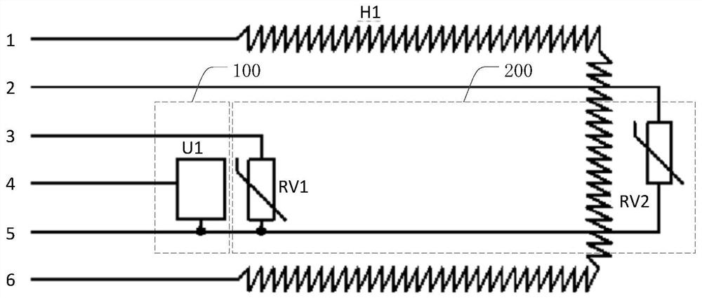
[0039] Specifically, see figure 1 The detection circuit 200 includes a first temperature sensor RV1 arranged at the air inlet end of the breathing tube and a second temperature sensor RV2 arranged at the air outlet end of the breathing tube, the input end of the first temperature sensor RV1 is connected to the first temperature sensor of the controller a power supply terminal (i.e. figure 1 The "3" terminal in ") is connected, and the input terminal of the second temperature sensor RV2 is connected with the second power supply terminal of the controller (ie figure 1 The "2" terminal in ") is connected, and the output terminal of the first temperature sensor RV1 and the output terminal of the second temperature sensor RV2 are both connected to the ground terminal of the controller (ie figure 1 "5" in the terminal) connection. The identification circuit 100 includes a multiplexing terminal, through which the multiplexing terminal is connected to the first control terminal of t...

Embodiment 2

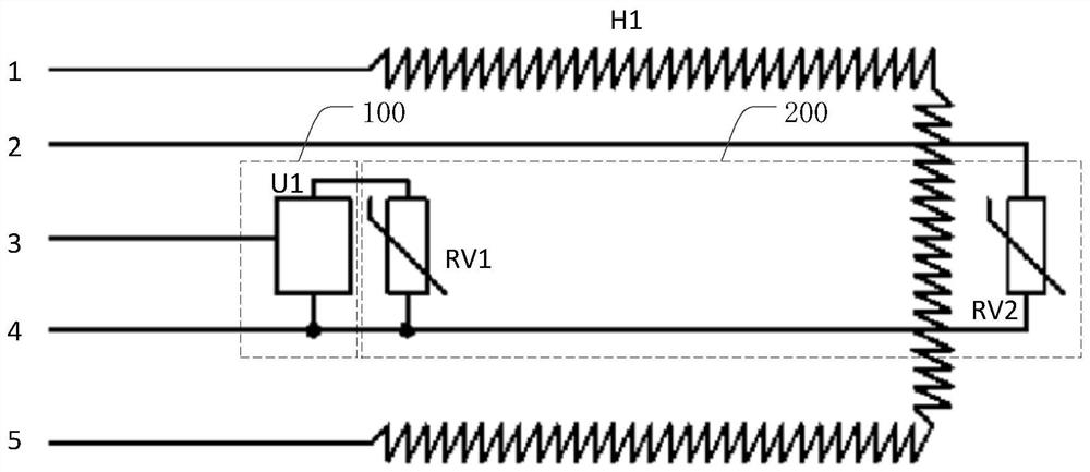
[0042] see figure 2 , in this embodiment, the detection circuit 200 includes a first temperature sensor RV1 arranged at the air inlet end of the breathing tube and a second temperature sensor RV2 arranged at the air outlet end of the breathing tube, the input end of the first temperature sensor RV1 is connected to the The identification circuit 100 is connected, and the input end of the second temperature sensor RV2 is connected to the second power supply end of the controller (ie figure 2 The "2" terminal in ") is connected, and the output terminal of the first temperature sensor RV1 and the output terminal of the second temperature sensor RV2 are both connected to the ground terminal of the controller (ie image 3 "4" in the terminal) connection. The identification circuit 100 includes a multiplexing terminal, through which the multiplexing terminal is connected to the first control terminal of the controller (ie figure 2 The terminal "3" in ) is connected, and the grou...

Embodiment 3

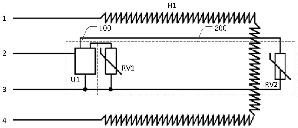
[0045] see image 3 , in this embodiment, the detection circuit 200 includes a first temperature sensor RV1 arranged at the air inlet end of the breathing tube and a second temperature sensor RV2 arranged at the air outlet end of the breathing tube, the input end of the first temperature sensor RV1 and the The input terminals of the second temperature sensor RV2 are connected to the identification circuit 100, and the output terminals of the first temperature sensor RV1 and the output terminal of the second temperature sensor RV2 are connected to the ground terminal of the controller ( which is image 3 "3" in the terminal) connection. The identification circuit 100 includes a multiplexing terminal, through which the multiplexing terminal is connected to the first control terminal of the controller (ie image 3 The terminal "2" in ) is connected, and the ground terminal of the identification circuit 100 is connected to the ground terminal of the controller.

[0046] During ...


PUM


Abstract

The invention discloses a respiratory tube temperature detection circuit, a temperature detection method and respiration assisting equipment. The respiratory tube temperature detection circuit comprises a detection circuit and an identification circuit; a controller controls a heating wire to heat gas in a respiratory tube; temperature data of a gas inlet end and a gas outlet end of the respiratory tube are detected by the detection circuit and are directly uploaded to the controller or stored into the identification circuit; the identification circuit stores a respiratory tube mark and/or thetemperature data and uploads the respiratory tube mark and/or the temperature data to the controller; and the identification circuit comprises a multiplexing end, and the controller performs power supply or communication on the identification circuit through the multiplexing end in a power supply and communication multiplexing manner. According to the respiratory tube temperature detection circuit, the temperature detection method and the respiration assisting equipment, port merging is achieved through uploading the temperature data and the respiratory tube mark by a power supply end of theidentification circuit in the power supply and communication multiplexing manner, or directly uploading the temperature data and uploading the respiratory tube mark through the multiplexing end of theidentification circuit in the power supply and communication multiplexing manner, and the occupation of interfaces of the controller is reduced.

Description

technical field [0001] The invention relates to the field of breathing assistance equipment, in particular to a breathing tube temperature detection circuit, a temperature detection method and breathing assistance equipment. Background technique [0002] Existing breathing aids (such as ventilators) are usually equipped with a variety of pipelines, each of which has an identification element and a temperature detection circuit. The detection circuit detects the temperature of the air inlet and outlet of the pipeline, and performs a corresponding breathing working mode. [0003] However, the identification element in the pipeline of the existing breathing aid equipment is connected in series with the heating wire in the pipeline, and the temperature detection circuit, the power supply of the identification element and the signal transmission of the pipeline are all completed through a separate line, occupying more interfaces of the controller, resulting in Waste of resources...

Claims


Application Information

Patent Timeline
Patent Type & Authority Applications(China)
IPC IPC(8): A61M16/00A61M16/10
CPCA61M16/0003A61M16/1095A61M2205/3368
Inventor 赵军徐结兵于海滨
Owner VINCENT MEDICAL (DONG GUAN) TECH CO LTD
Why Eureka
Try Eureka