Liquid Discharge Apparatus, Liquid Discharge Method and Non Transitory Computer-Readable Medium

A liquid discharge and equipment technology, applied in printing, printing devices, inking devices, etc., can solve the problem of no ink circulation, etc., achieve the effect of reducing power consumption and heat generation, and suppressing the deterioration of image quality

Active Publication Date: 2021-02-02
BROTHER KOGYO KK
View PDF6 Cites 0 Cited by
  • Summary
  • Abstract
  • Description
  • Claims
  • Application Information

AI Technical Summary

Problems solved by technology

When power is not supplied from an external power source, an inkjet printer uses power from the battery to perform the precursor, but there is no ink circulation

Method used


Image

  • Liquid Discharge Apparatus, Liquid Discharge Method and Non Transitory Computer-Readable Medium
  • Liquid Discharge Apparatus, Liquid Discharge Method and Non Transitory Computer-Readable Medium
  • Liquid Discharge Apparatus, Liquid Discharge Method and Non Transitory Computer-Readable Medium

Examples


no. 1 example

[0037]

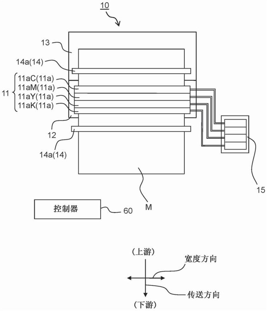
[0038] As the liquid discharge apparatus 10 according to the first embodiment (see figure 1 and figure 2 ), an inkjet printer that performs printing on a recording medium M by discharging ink is explained below. The liquid discharge device 10 is not limited to an inkjet printer that discharges ink as liquid. The liquid discharge device 10 may be a liquid discharge device that discharges any liquid other than ink.

[0039] The liquid discharge apparatus 10 of the line head system is employed in the first embodiment. The liquid discharge apparatus 10 includes a head unit 11 , a platen 12 , a tray 13 , a conveyor 14 , a storage tank 15 and a controller 60 . The head unit 11 includes one or more (for example, four) discharge heads 11a. The discharge head 11a is longer than the recording medium M in the width direction.

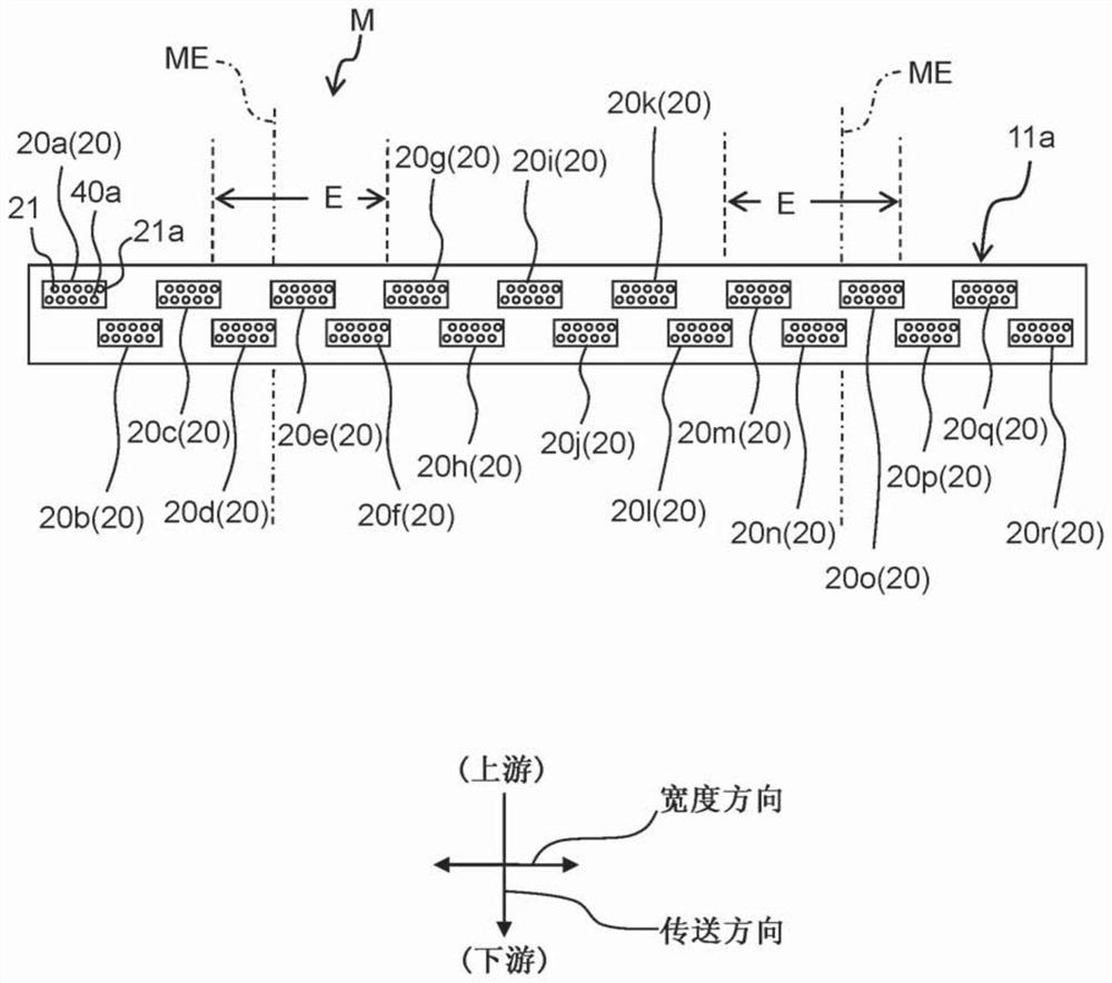
[0040] Each discharge head 11a includes a passage forming body and a volume changing portion. The inside of the channel-forming body is provided...

no. 2 example

[0141] Such as Figure 12 As depicted in , the liquid discharge device 10 according to the second embodiment includes a temperature sensor 70 that detects the temperature in the liquid discharge device 10 . Any other configuration than the temperature sensor 70 is similar to that in the first embodiment, and thus an explanation thereof is omitted.

[0142] The temperature sensor 70 is a sensor that detects the temperature of air in contact with the meniscus of ink formed in the nozzle hole 21 a of the head chip 20 . For example, the temperature sensor 70 is provided in the discharge head 11 a in the liquid discharge apparatus 10 . The temperature sensor 70 detects the temperature around the discharge head 11 a , which is the temperature in the liquid discharge apparatus 10 . The detected temperature may be corrected based on a predetermined correspondence between the detected temperature and the temperature in the vicinity of the nozzle hole 21a.

[0143] When the detection...

no. 3 example

[0151] Such as Figure 12 As depicted in , the liquid discharge device 10 according to the third embodiment includes a humidity sensor 80 that detects humidity in the liquid discharge device 10 . Any other configuration than the humidity sensor 80 is similar to that in the first embodiment, and thus an explanation thereof is omitted.

[0152] The humidity sensor 80 is a sensor that detects the humidity of air in contact with the meniscus of ink formed in the nozzle hole 21 a of the head chip 20 . For example, the humidity sensor 80 is provided in the discharge head 11 a in the liquid discharge apparatus 10 . The humidity sensor 80 detects the humidity around the discharge head 11 a , which is the humidity in the liquid discharge apparatus 10 . The detected humidity may be corrected based on a predetermined correspondence between the detected humidity and the humidity in the vicinity of the nozzle hole 21a.

[0153] When the detected humidity detected by the humidity sensor ...


PUM


Abstract

The invention provides a liquid discharge apparatus, a liquid discharge method and a non transitory computer-readable medium. There liquid discharge apparatus includes: a conveyer; head chips; a circulation channel; and a controller. Each head chip includes a manifold; a nozzle group, and actuators. Each head chip is configured to execute discharge drive and non-discharge vibration drive. The headchips include: an end head chip; a facing head chip facing the recording medium; and a non-facing head chip not facing the recording medium. The controller is configured to make at least one of a circulation flowing amount of a liquid in the circulation channel in the facing head chip and a frequency of the non-discharge vibration drive by an actuator included in the actuators in the facing headchip larger than those of the non-facing head chip. The medium stores a control program corresponding to the method.

Description

technical field [0001] The present disclosure relates to a liquid discharge device, a liquid discharge method, and a non-transitory computer-readable medium storing a control program for the liquid discharge device. Background technique [0002] There is conventionally known an inkjet printer including: an inkjet head including nozzles; a circulation channel through which ink circulates between the inkjet head and a tank; and a battery storing electric power for maintenance. When power is supplied to the inkjet printer from an external power source, the inkjet printer performs a precursor for applying vibration to ink without discharging ink from nozzles, and circulates ink through a circulation channel. When power is not supplied from an external power source, the inkjet printer performs a precursor using power from a battery, but there is no ink circulation. Contents of the invention [0003] In the inkjet printer described above, maintenance methods for dealing with im...

Claims


Application Information

Patent Timeline
Patent Type & Authority Applications(China)
IPC IPC(8): B41J2/01B41J2/18B41J29/38B41J2/175B41J2/135B41J2/11
CPCB41J2/01B41J2/18B41J29/38B41J2/17503B41J2/135B41J2/11B41J2/175B41J2202/12B41J2202/21B41J2202/20B41J2/14233B41J2002/14419B41J2/17509B41J2/16585B41J2/04596B41J2/04581B41J2/04595B41J2/04588
Inventor 野津知广伊藤祐一
Owner BROTHER KOGYO KK
Why Eureka
Try Eureka