Water surface transportation tool

A technology of transportation tools and cabins, which is applied in the field of transportation, and can solve problems such as the increase in the amplitude of the swing of the ship, the displacement of the cargo box, and the drop of the cargo box into the water, so as to increase the friction, reduce the amplitude, and avoid side effects. slippery effect

Inactive Publication Date: 2021-02-02
广州鑫呈信息技术有限公司
View PDF0 Cites 0 Cited by
  • Summary
  • Abstract
  • Description
  • Claims
  • Application Information

AI Technical Summary

Problems solved by technology

[0003] Based on the inventor's discovery above, the existing a kind of water surface transport mainly has the following deficiencies, such as: because the food supplied to the masses is to be packed in square cartons, the cartons are carried on the boat by overlapping and swinging. When the cargo ship travels to waters with relatively turbulent water flow, the swing of the ship's hull will also increase, causing the container placed on the top to be displaced, causing the container to fall into the water

Method used


Image

  • Water surface transportation tool
  • Water surface transportation tool
  • Water surface transportation tool

Examples


Embodiment 1

[0026] Example 1: Please refer to Figure 1-Figure 5 , the specific embodiments of the present invention are as follows:

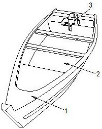
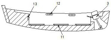
[0027] Its structure includes a hull 1, a cabin 2, and an engine 3. A cabin 2 is arranged in the middle of the hull 1. The engine 3 is installed at the rear end of the hull 1. The cabin 2 includes a fixing seat 11 and a rope tying block 12. , barb 13, described fixed seat 11 is provided with three and is installed in the inner end of cabin 2 transversely, and described rope block 12 is provided with two, and is installed in the both sides of cabin 2 respectively, and described barb 13 Embedded in the front end of the cabin 2.

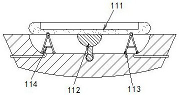
[0028] The fixed seat 11 includes a mounting seat 111, a rotating disk 112, a movable rod 113, and a tension spring 114. The bottom of the mounting seat 111 is provided with a rotating disk 112, and the rotating disk 112 is engaged in the cabin 2. The movable rod 113 There are four, and two by two are installed on the two ends of ...

Embodiment 2

[0032] Example 2: Please refer to Figure 6-Figure 8 , the specific embodiments of the present invention are as follows:

[0033] The mounting base 111 includes a loading groove b1, a clamping arm b2, a sliding groove b3, and a support plate b4. The two ends of the loading groove b1 are provided with a clamping arm b2, and the sliding groove b3 is provided with two, and are respectively located at both ends of the bottom of the loading trough b1. There are two support plates b4 located at both ends of the bottom of the loading trough b1. The support plates b4 are engaged in the sliding trough b3, which is conducive to placing the goods On the supporting plate b4, when the clamping arm b2 clamps the goods, the supporting plate b4 can move along with the goods.

[0034] The support plate b4 includes a board body b41, an engaging foot b42, and a rubber pad b43. The bottom of the board body b41 is provided with an engaging foot b42, and the engaging foot b42 is movably matched wi...


PUM


Abstract

The invention discloses a water surface transportation tool which structurally comprises a ship body, a cabin and an engine, the cabin is arranged just in the middle of the interior of the ship body,the engine is installed at the rear end of the ship body, the cabin comprises a fixed base, a rope binding block and a barb, the fixed base comprises an installation base, a rotary disc, a movable rodand an extension spring, the rotary disc comprises a rotary groove, a friction pad, a rotary rod and a friction wheel, and the friction pad comprises a friction body, a deformation groove and a fixedblock. According to the invention, the fixed base is arranged in the cabin, then goods are installed on the installation seat, when the ship body swings, the movable rod can make contact with the wavy end face in the friction body, the friction force is increased, and the swing amplitude of the installation seat along with the ship body can be reduced; and the condition that the goods loaded in the cabin fall into water is avoided.

Description

technical field [0001] The invention relates to the field of transportation, in particular to a water surface transportation tool. Background technique [0002] Surface transportation refers to tools that can transport goods on the sea or in rivers. After a flood, the water level rises, causing floods to submerge houses, and people are trapped in the flood. At this time, goods need to be transported to temporary resettlement of the people. Dot, feed the masses. [0003] Based on the inventor's discovery above, the existing a kind of water surface transport mainly has the following deficiencies, such as: because the food supplied to the masses is to be packed in square cartons, the cartons are carried on the boat by overlapping and swinging. When the cargo ship travels to waters with relatively turbulent water flow, the swing of the hull will also increase, causing the cargo box placed on the top to be displaced, causing the cargo box to fall into the water. Contents of th...

Claims


Application Information

Patent Timeline
IPC IPC(8): B63B25/24B63B25/22
CPCB63B25/22B63B25/24
Inventor 李尚
Owner 广州鑫呈信息技术有限公司
Why Eureka
Try Eureka