Universal rapid positioning detection tool for radiographic inspection of welded structural part

A technology of ray detection and welding structure, which is applied in the field of general rapid positioning and detection tooling, can solve the problems of inconvenient ray detection incidence angle and angle positioning, and achieve the effects of rapid adjustment of ray incidence angle, rapid installation and positioning, and improvement of radiation detection efficiency

Active Publication Date: 2021-02-02
JIANGXI CHANGHE AVIATION IND
View PDF6 Cites 0 Cited by
  • Summary
  • Abstract
  • Description
  • Claims
  • Application Information

AI Technical Summary

Problems solved by technology

[0003] The purpose of the present invention is to provide a universal rapid positioning detection tool for the radiation detection of welded structural parts, which can quickly adjust the incident angle of radiation, quickly position the parts, improve work efficiency, reduce detection costs, and overcome the inconvenience of the previous part positioning operation The problem of poor positioning of the incident angle and angle of ray detection

Method used


Image

  • Universal rapid positioning detection tool for radiographic inspection of welded structural part
  • Universal rapid positioning detection tool for radiographic inspection of welded structural part
  • Universal rapid positioning detection tool for radiographic inspection of welded structural part

Examples


Embodiment 1

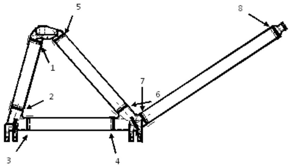
[0020] Embodiment 1, to figure 1 Radiographic inspection of No. 3 weld seam.

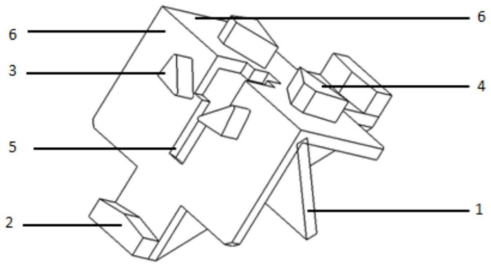
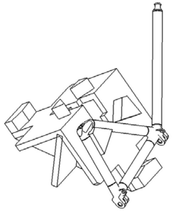
[0021] Found in the inspection tooling figure 2 As shown in the supporting surface of the assembled top block 4, press Figure 3a Place the weldment on the support surface of the tooling device as shown, and place the part in place;

[0022] Adjust the horizontal position of the circular tube where the weld seam is located on the base 2 according to the requirements of the radiographic inspection, and adjust the incident angle of rays required for the weld seam inspection;

[0023] After the parts are positioned, the No. 1 weld seam is transilluminated and arranged, and then the weld seam is subjected to radiographic inspection.

Embodiment 2

[0024] Embodiment 2, to figure 1 Radiographic Inspection of No.5 Weld Seam

[0025] Found in the inspection tooling figure 2 on groove 5 shown, press Figure 3b Place the weldment at the opening at the lowermost end of the groove as shown, and place the part in place;

[0026] According to the requirements of the incident angle of the ray detection, adjust the horizontal position of the circular tube where the weld seam is located in the groove 5, and adjust the incident angle of the weld seam;

[0027] After the parts are positioned, the No. 5 weld seam is arranged for transillumination, and the weld seam is subjected to radiographic inspection.

Embodiment 3

[0028] Embodiment 3, to figure 1 Radiographic Inspection of No. 2 Weld Seam

[0029] Found in the inspection tooling figure 2 As shown in the supporting surface 6 of the assembled top block 3, press Figure 3c Place the weldment on the support surface of the tooling device as shown, and place the part in place;

[0030] Adjust the horizontal position of the circular tube where the weld seam is located on the base 2 according to the requirements of the radiographic inspection, and adjust the incident angle of rays required for the weld seam inspection;

[0031] After the parts are positioned, the No. 2 weld seam is arranged for transillumination, and then the weld seam is subjected to radiographic inspection.

[0032] The positioning detection of the tooling of the present invention includes: step 1, according to the weld seam that needs to be detected in the welding structure, place the part on the support surface, fix it on the top block or place it in the groove for posi...


PUM


Abstract

The invention belongs to the technical field of radiographic inspection application, and particularly relates to a universal rapid positioning detection tool for radiographic inspection of a welded structural part. The tool comprises a base body, bases, an ejector block, right-angle supporting faces and a groove. The base body is fixed in an included angle formed by the right-angle supporting faces and forms 45 DEG included angles with the two supporting faces of the right-angle supporting faces, the groove is formed in the middle of the included angle, the width of an opening in the lowermostend of the groove is larger than the outer diameter of a part, and therefore the ray incident angle can be flexibly adjusted and the part can be fixed conveniently; each supporting face is provided with a top block; and one base is assembled at the bottom of each supporting face.

Description

technical field [0001] The invention belongs to the technical field of radiation detection applications, and in particular relates to a universal rapid positioning detection tool for radiation detection of welded structural parts. Background technique [0002] A metal structural part is welded by round tubes of different lengths and different joints, and the space size is large (see figure 1 ). When performing radiographic inspection on the welds of this structural part, it is necessary to use multiple wooden blocks of different sizes to support and position the parts; in addition, because there is a requirement for the incident angle of rays during weld inspection, the parts are supported and the incident angle of rays is adjusted. Afterwards, it takes a long time to locate the parts, especially the radiographic inspection of the pipe welds in the triangular area, which seriously affects the detection efficiency and cannot meet the requirements of batch inspection of parts...

Claims


Application Information

Patent Timeline
Patent Type & Authority Applications(China)
IPC IPC(8): G01N23/04
CPCG01N23/04G01N2223/33
Inventor 胡保花朱洪达
Owner JIANGXI CHANGHE AVIATION IND
Why Eureka
Try Eureka