
Electronic component operation device and operation classification equipment applying same

A technology of electronic components and operating devices, which is applied in the direction of measuring devices, measuring device casings, connecting devices, etc., and can solve problems that affect the quality of electronic component testing and cannot be reliably contacted.

Pending Publication Date: 2021-02-02
HON PRECISION INC
View PDF6 Cites 0 Cited by
  • Summary
  • Abstract
  • Description
  • Claims
  • Application Information

AI Technical Summary

Problems solved by technology

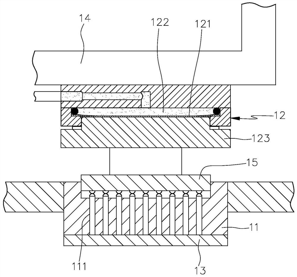
[0003] see figure 1 , is a schematic diagram of the test seat 11 and the crimping device 12 of the operating device, the test seat 11 is provided with a plurality of probes 111, and is electrically connected to a circuit board 13 to test electronic components; the crimping device 12 is assembled on the moving arm 14 , to transfer the electronic component 15 to be tested to the test socket 11, the interior of the crimping device 12 is provided with a diaphragm 121, an air chamber 122 and a pressing fixture 123, etc. After the gas is injected into the chamber 122, the diaphragm 121 protrudes and deforms downward, and pushes the pressing jig 123 to move downward in the Z direction to press down the electronic component 15, so that the electronic component 15 can perform the test operation in the test seat 11; But because the springs (not shown) of tens of probes 111 of test socket 11 are compressed, tens of probes 111 will produce a larger reaction force to electronic component 15, this larger reaction force Pushing through the electronic component 15 drives the crimping device 12 to reversely displace in the Z direction, resulting in the problem that the crimping device 12 cannot be pressed against the electronic component 15 with the preset downward force, so that some contacts of the electronic component 15 The probe 111 of the test socket 11 cannot be reliably contacted, thereby affecting the test quality of the electronic components

Method used


Image

  • Electronic component operation device and operation classification equipment applying same
  • Electronic component operation device and operation classification equipment applying same
  • Electronic component operation device and operation classification equipment applying same

Examples


Embodiment Construction

[0016] For a further understanding of the present invention, a preferred embodiment is hereby given in conjunction with the drawings, which are described in detail as follows:

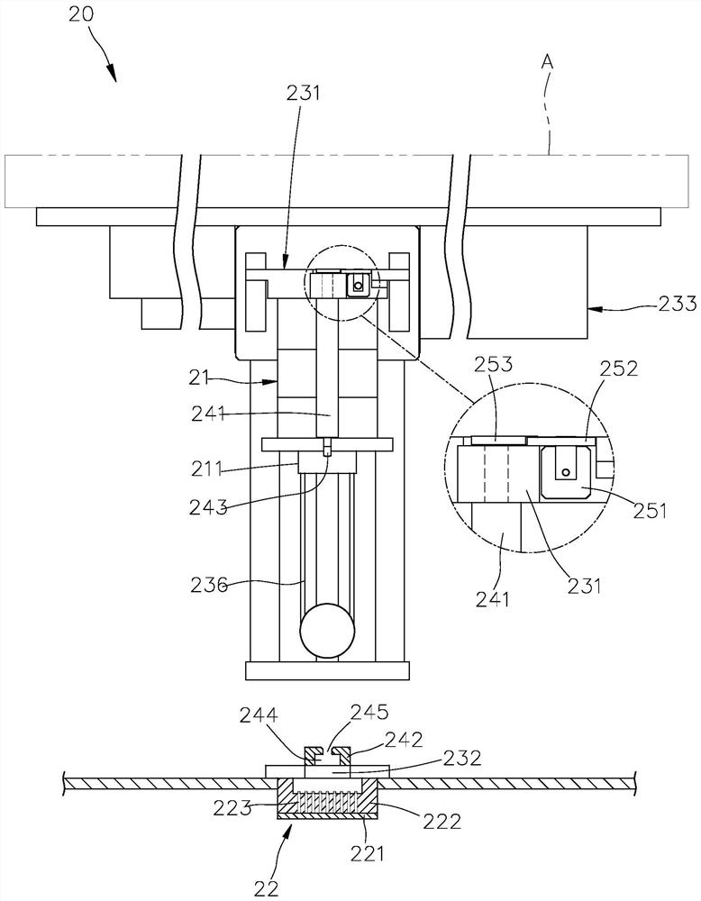
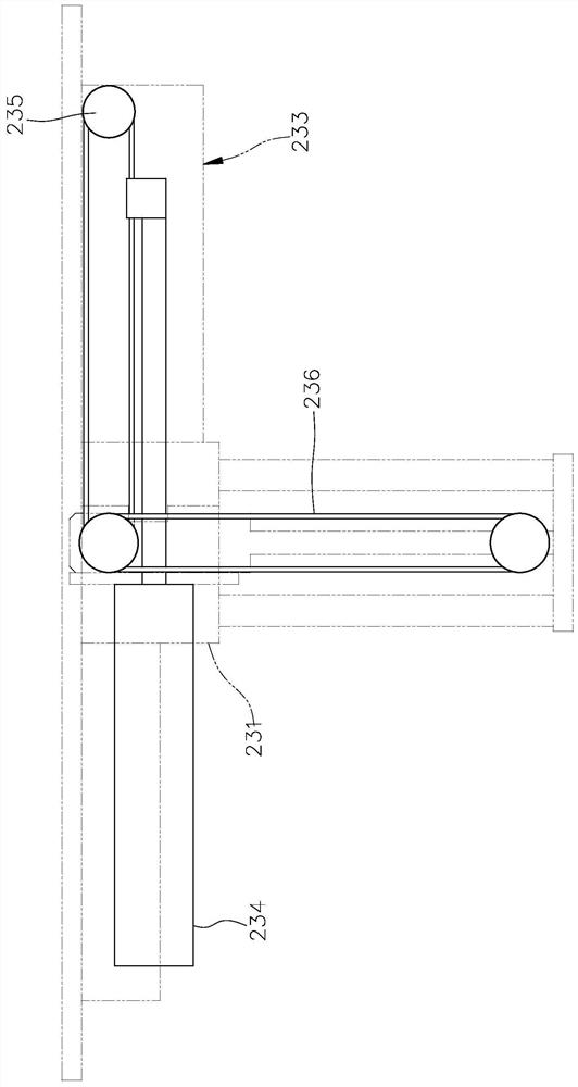
[0017] see figure 2 , image 3 , Figure 4 , the electronic component operation device 20 of the present invention includes at least one operator and actuating mechanism, the operator performs preset operations on the electronic components, further, the operator can be a crimping device, a tester, a printer, etc., in this embodiment Among them, the working device 20 includes a first working device and a second working device, the first working device is arranged in the actuating mechanism, and is a crimping device 21, and the crimping device 21 is provided with at least one crimping part 211 that can be displaced in the Z direction , to carry out the operation of pressing down the electronic components, and the other operating device 20 can be provided with a temperature controller on the crimping d...


PUM


Abstract

The invention discloses an electronic component operation device and operation classification equipment applying the same, the electronic component operation device comprises an operator and an acknowledgement mechanism, the acknowledgement mechanism is provided with a bearing unit, a fastening unit and a driving unit, the bearing unit is used for assembling the operator through a first bearing tool, a second bearing tool is arranged in an operation area, and the fastening unit is used for fastening the operator through the second bearing tool. The fastening unit is provided with a first acknowledgement tool on the first bearing tool and a second acknowledgement tool on the second bearing tool, the first acknowledgement tool and the second acknowledgement tool are provided with a first fastening component and a second fastening component which can be fastened with each other, and the driving unit is provided with a driving source for driving the first acknowledgement tool or the secondacknowledgement tool to rotate. Therefore, the first buckling part of the first determining tool and the second buckling part of the second determining tool are mutually buckled so as to prevent thewhole operation device from being pushed reversely by the electronic element to move, the operation device is enabled to execute preset operation on the electronic element indeed, and the practical benefit of improving the operation quality is achieved.

Description

technical field [0001] The invention provides an operation device which can make an operation device execute a preset operation on electronic components, thereby improving the operation quality. Background technique [0002] Nowadays, the number of contacts of electronic components is increasing day by day, ranging from a few to dozens. Correspondingly, the test socket of the operating device must also be equipped with the same number of probes to electrically contact the contacts of electronic components; There is a spring inside the needle. In order to make electrical contact between the contact point of the electronic component and the probe of the test socket, the operating device must make a crimping device press the electronic component with a pressure, so that the electronic component compresses the probe. However, the excessive or insufficient down force of the crimper will affect the quality of the test. For example, when the electronic component has dozens of conta...

Claims


Application Information

Patent Timeline
Patent Type & Authority Applications(China)
IPC IPC(8): G01R1/04G01R31/01H01R43/26
CPCG01R1/04G01R1/0416G01R31/01H01R43/26H01R2201/20
Inventor 李子玮陈永仓
Owner HON PRECISION INC
Learn More