Device for transmitting and/or receiving a message in a combined assisted and ad-hoc mode

A technology for sending messages and auxiliary mode, applied in the field of mobile communication, which can solve problems such as activation, establishment, or configuration without consideration, and achieve the effect of reduced redundancy and high data rate

Pending Publication Date: 2021-02-09
HUAWEI TECH CO LTD
7 Cites 0 Cited by

AI-Extracted Technical Summary

Problems solved by technology

In both cases, prior art methods and signaling focus only on one specific radio interface (i.e., assisted mode), w...

Method used

[0203] As shown in FIG. 2A , the device 100 can also be used to transmit a message 101 through an assisted mode 102 and to transmit a message 101 through an ad-hoc mode 103 in a combined assisted and ad-hoc mode 104. In other words, the device 100 can use the auxiliary mode 102 and the ad-hoc mode 103 to increase the redundancy of the link. The device can be used to copy the message 101 and send the message 101 through the assisted mode 102 and a copy of the message through the ad-hoc mode 103 .
[0204] Increasing the redundancy of the links helps, for example, to increase the reliability of communications. In this case, each data packet (eg each message) of a service or data flow (eg V2X service) between two or more UEs or vehicles is sent in assisted mode and ad-hoc mode (replication).
[0206] In other words, the device 100 can use the auxiliary mode 102 and the ad-hoc mode 103 for link aggregation. That is, by splitting the message stream, the first message 101-1S is sent via one mode, and the second message 101-2S ​​is sent via another mode (preferably simultaneously), thereby increasing message throughput and reducing message delay.
[0210] In other w...

Abstract

The present invention relates to the field of mobile communication, in particular vehicle-to-anything (V2X) communication, and provides a device (100) for transmitting a message (101) over a wirelesscommunication system, in particular a UE, wherein the device (100) is configured to select one of an assisted mode (102), an ad-hoc mode (103), or a combined assisted and ad-hoc mode (104); and transmit the message (101) over the selected mode. To support bi-directional transmission, the present invention also provides a device (1500) for receiving a message (1501) over a wireless communication system, in particular a UE, wherein the device (1500) is configured to select one of an assisted mode (1502), an ad-hoc mode (1503), or a combined assisted and ad-hoc mode (1504); receive the message (1501) over the selected mode. The present invention also provides a management device (1700), in particular a network device, for supporting a device for transmitting and/or receiving a message over awireless communication system.

Application Domain

Particular environment based servicesNetwork topologies +4

Technology Topic

Embedded systemCommunications system +1

Image

  • Device for transmitting and/or receiving a message in a combined assisted and ad-hoc mode
  • Device for transmitting and/or receiving a message in a combined assisted and ad-hoc mode
  • Device for transmitting and/or receiving a message in a combined assisted and ad-hoc mode

Examples

  • Experimental program(1)

Example Embodiment

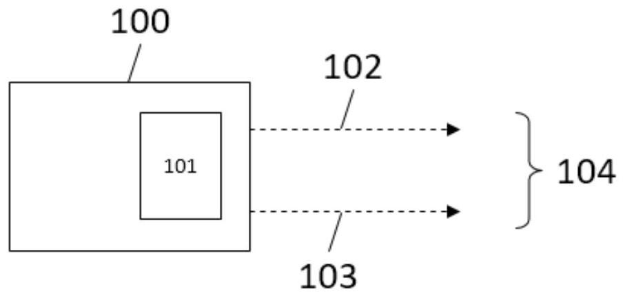
[0183] figure 1 Shown is a device 100 for sending a message (eg user plane data packet) 101 over a wireless communication system. The device 100 may in particular be a UE, for example a UE used in a vehicle, or a vehicle. To send the message 101 , the device 100 is configured to select one of the assisted mode 102 , the ad-hoc mode 103 , and the combined assisted and ad-hoc mode 104 . The above-mentioned selection may also include specification of one or more resources related to the selected mode, such as a predefined resource block for the assisted mode. After the selection has been performed, the message 101 is sent via the selected mode. This selection may eg be an initial selection, ie the mode is selected for the first time (eg at start-up). The selection may also include, for example, changing the currently used mode to the newly selected mode.
[0184] In other words, the device 100 enables an initial selection of a communication mode (which may include session/connection establishment) for a service, especially a V2X service. The mode can be an assisted mode (eg cellular or Uu), an ad-hoc mode (eg sidelink or PC5), or a combined assisted and ad-hoc mode (eg cellular or Uu and sidelink or PC5). Furthermore, the device 100 allows dynamic switching of communication modes during the lifecycle of the service. That is, during operation, the mode can be re-selected, for example, the selection is initiated by the network based on a request received from the network-side device (such as the management device), and the selection can also be initiated by the UE based on the determination of the device 100 itself.
[0185] Additionally, device 100 acquires an assisted mode (e.g., cellular or Uu), and/or an ad-hoc mode (e.g., sidelink or PC5), and/or a combined assisted and ad-hoc mode (e.g., cellular or Uu and sidelink road or PC5) availability indication.
[0186] The availability indication may be used by the device 100 to determine whether to send a message; and/or to select one of assisted mode, ad-hoc mode, or a combined assisted and ad-hoc mode and send a message through the selected mode; and/or to manage the communication link road.
[0187] In addition, device 100 may use the aforementioned availability indications to determine whether to establish a communication session or link; and/or to manage communication failures; and/or to safely release communication and/or application services; and/or to reconfigure communications with one or more devices. communication. For example, the UE may switch to another communication mode based on the aforementioned availability indication, so as to ensure service continuity such as V2X services.
[0188] Device 100 may obtain the availability indication by determining the availability indication, eg, by generating, and/or calculating, and/or estimating the availability indication based on any selection criteria.
[0189] Alternatively, the device 100 may obtain the availability information by receiving the availability information from another device 100 and/or another device 1500 and/or the management device 1700 .
[0190] For example, the ad-hoc mode (such as side link or PC5 ) availability indication. In another example, the indication of availability of the secondary mode (eg cellular or Uu) may be obtained using the cell selection criteria S and/or cell loading measured by the device 100 .
[0191] In order for the device 100 to obtain the availability indication based on the selection criteria, the above at least one selection criterion may be pre-stored in the device 100, and/or determined by the device 100, and/or provided to the device 100 from outside.
[0192] The device 100 may send the above availability indication to the management device; and/or to another device; and/or to a network entity (such as a base station); and/or to an application function inside or outside the network operator.
[0193] The device 100 may obtain the above availability indication for at least one of the following configurations or a combination of these configurations:
[0194] By communication interface/mode (cellular, sidelink),
[0195] By radio access technology (e.g. 5G, 4G, IEEE 802.11p),
[0196] By service type or category (e.g., safety, platooning, sensor sharing, amenities, autonomous driving, etc.), since different services can have different QoS requirements,
[0197] · By carrier,
[0198] · By resource pool,
[0199] · By service quality level or category,
[0200] ·By business type, such as unicast, multicast, broadcast.
[0201] To obtain an availability indication for any of the above configurations, the device 100 may use selection criteria available at the UE and/or provided by neighboring UEs and/or network equipment. For example, to obtain availability indications by service type and by communication interface/mode, device 100 uses wireless measurements of different communication interfaces (e.g. PC5, Uu) and monitored QoS information for different types of services (e.g. security, premium, platooning, etc.) .
[0202] figure 2 Shown in more detail (specifically in figure 2 A. figure 2 B. figure 2 In C) Device 100 according to an embodiment of the invention. figure 2 The device 100 includes figure 1 All features and functions of the device 100. For this reason, identical features are marked with the same reference numerals. will be figure 2 All features described in are optional features of device 100.
[0203] like figure 2 As shown in A, the device 100 can also be used to transmit the message 101 through the assisted mode 102 and to transmit the message 101 through the ad-hoc mode 103 in a combined assisted and ad-hoc mode 104 . In other words, the device 100 can use the auxiliary mode 102 and the ad-hoc mode 103 to increase the redundancy of the link. The device can be used to copy the message 101 and send the message 101 through the assisted mode 102 and a copy of the message through the ad-hoc mode 103 .
[0204] Increasing the redundancy of the links helps, for example, to increase the reliability of communications. In this case, each data packet (eg each message) of a service or data flow (eg V2X service) between two or more UEs or vehicles is sent in assisted mode and ad-hoc mode (replication).
[0205] like figure 2 As shown in B, the device 100 can also be used to send the first message 101-1S through the assisted mode 102 and the second message 101-2S ​​through the ad-hoc mode 103 in the combined assisted and ad-hoc mode 104.
[0206] In other words, device 100 can use auxiliary mode 102 and ad-hoc mode 103 for link aggregation. That is, by splitting the message stream, the first message 101-1S is sent via one mode, and the second message 101-2S ​​is sent via another mode (preferably simultaneously), thereby increasing message throughput and reducing message delay.
[0207] Link aggregation (which can also be called dual connectivity mode) helps e.g. to increase throughput and reduce latency: in this case, a link between two or more UEs or vehicles is sent on Different packets/messages for services or flows (e.g. V2X services). The exact configuration of the split between one mode and the other (e.g. the percentage or number of packets/messages that should be sent via one mode or the other) can be decided by the device 100 (e.g. a UE) , or received by the device 100 from a network side device (such as a management device).
[0208] More specifically, the first message 101-1S and the second message 101-2S ​​may belong to the same service S, for example, the same V2X service.
[0209] like figure 2 As shown in C, the device 100 can also be used to, in the assisted and ad-hoc combined mode 104, split the message 101 into a first part 101a and a second part 101b, and send the first part 101a through the assisted mode 102, and send the first part 101a through the ad-hoc The hoc mode 103 sends the second part 101b.
[0210] In other words, device 100 can use auxiliary mode 102 and ad-hoc mode 103 for link aggregation. That is, by splitting the message, sending the first part 101a via one mode, and sending the second message 101b via another mode (preferably at the same time), the throughput of the message is increased and the latency of the message is reduced.
[0211] In this example, link aggregation helps, for example, to increase throughput and reduce latency. Different packets/messages of a service or flow (eg V2X service) between two or more UEs or vehicles are sent on both interfaces (split).
[0212] image 3 (exist image 3 A and image 3 Middle B) shows two views of multipath communication, where both modes are used for communication between two or more vehicles. image 3 A involves figure 2 A description and instructions, while image 3 B involves figure 2 B and figure 2 C instructions and descriptions. That is to say, image 3 B shows link aggregation in a more abstract way, without distinguishing whether to split the message flow or to split each message.
[0213] as will now refer to Figure 4 As described, the dynamic switching of communication modes selected between two or more UEs or vehicles in the context of the same service is used to maintain and guarantee the required QoS during the lifetime of a particular service. Figure 4 An example of dynamic switching of communication modes for V2X services is shown. The dynamic switching may be network initiated or UE initiated. In the context of the same service, a group of related UEs or vehicles can use different combinations of communication modes according to their QoS requirements and current network and road conditions.
[0214]The decision to dynamically select and/or switch the appropriate communication mode can be made at the BS, e.g. via RRC messages or any other core network entity (e.g. access and mobility function (AMF) in a 5G communication network, A session management function (session management function, SMF), or a V2X control function). This can also be done by a cloud server or a mobile edge computing (MEC) server taking into account the QoS requirements of the V2X service and the current network conditions (e.g. network load) as well as wireless information for each communication interface of the corresponding cell and/or neighboring cells To be done.
[0215] Figure 5 An example of a scheme that may be used to select or switch an appropriate communication mode is shown.
[0216] To select an appropriate communication mode, the device 100 may also be used to select a mode based on a configuration defining the mode to be used for the message 101 . That is, depending on the message type, a mode may be selected by the device 100 . Thus, the configuration may be pre-stored in the device 100, and/or determined by the device 100, and/or provided to the device 100 from outside.
[0217] In order to select an appropriate communication mode, the device 100 can also be used to select a mode based on at least one of the following selection criteria: QoS information; service type parameters (i.e. parameters defining the mode required for the service); the mobile device concerned, In particular vehicle, and/or information based on other mobile devices or vehicles; wireless information, in particular channel measurements; or location information and/or routing information.
[0218] The device 100 may also be configured to send at least one of the above selection criteria to the management device. Accordingly, the device 100 previously obtained the corresponding selection criteria. In the management device, selection criteria can be used for mode selection to coordinate and improve the overall QoS of the communication system managed by the management device.
[0219] In order for the device 100 to make a decision based on the selection criteria, the above at least one selection criterion may be pre-stored in the device 100, and/or determined by the device 100, and/or provided to the device 100 from outside.
[0220] The device 100 may also be configured to receive a mode selection request, and select a mode based on the received mode selection request, or actively select a mode.
[0221] The QoS information on which the mode selection is based may comprise a mapping between first QoS parameters and second QoS parameters, preferably wherein the first QoS parameters relate to the assisted mode 102 and wherein the second QoS parameters relate to the ad-hoc mode 103 . The map can be pre-stored or generated in the device, or the map can be provided from the network. This mapping concept will be referred to in the following Image 6 described in more detail.
[0222] The device 100 is also operable to perform a selection step related to at least one of the following layers: application layer; service data adaptation protocol (SDAP layer); packet data convergence protocol (PDCP) layer; radio link control (RLC) layer ; or the Media Access Control (MAC) layer. In particular, a configuration (such as one of the above configurations) received from another device, in particular a network device, may depend on a particular layer. Preferably, if the above selection step (eg, routing) is performed at the application layer, the device 100 may include an interface for forwarding the selected mode and/or configuration from the network layer to the application layer. This concept will be referred to in the following Figure 12 to Figure 14 described in more detail.
[0223] refer to Image 6 , the concept of mapping between the first QoS parameter and the second QoS parameter is now described in detail. As mentioned above, different communication modes may have different QoS schemes and mechanisms. Integration of assisted mode and ad-hoc mode may require integration of QoS schemes. For example, in a 5G communication system, for V2X communication via cellular Uu interface, NG-RAN and 5GC guarantee QoS by mapping packets to appropriate QoS flows and dedicated radio bearers (DRBs). For example as described in 3GPP15-23501, DRB is selected based on 5QI (ie Service Requirement) and uses 2-step mapping of IP flow to QoS flow (NAS) and from QoS flow to DRB (Access Stratum). On the other hand, for the V2X communication via the sidelink PC5, sidelink quality information is provided via ProSe per-packet priority (PPPP) and adjacent traffic packet reliability (ProSe per-packet reliability, PPPR). PPPP and PPPR are selected by the application layer. A packet delay budget (PDB) of a protocol data unit may be determined from PPPP. The existing PPPP-based logical channel priority is used for V2X sidelink communication.
[0224] In cases where the communication modes may have different QoS schemes, a regular mapping between cellular (Uu) QoS information and sidelink (PC5) QoS information applies. E.g, Image 6 An example of mapping between 5QI and PPPP is shown. These mapping rules can be predefined/specified in the device, or provided by the network (distributed on the site). In case these rules are predefined, these rules can be stored at UE/vehicle side or at V2X application server. Alternatively, these rules can be extracted from the network (eg PCF, SMF of a 5G network) using a service request or during initial attachment.
[0225] Alternatively, the same QoS information or scheme can be used by both communication modes. For example, 5QI and/or radio bearers used for the cellular (Uu) interface may also be used by the sidelink interface.
[0226] refer to Image 6 The disclosure of the above applies to the figure 1 device 100, and apply the following Figure 15 The device 1500 and Figure 17 The device 1700.
[0227] refer to Figure 7 , Figure 8 ,as well as Figure 9 , the selection of the communication mode is now described in detail. The UE, vehicle, or application server requests to establish a connection or add a new communication link to support the initiated V2X service. As mentioned above, the sidelink (PC5) and cellular (Uu) links use different signaling to establish one or the other communication mode. The invention allows a device to select a more suitable communication mode, inter alia by using and/or extending an initial request, which may come from a UE, a vehicle, or an application server. The request may also include requested QoS, preferred mode, or related UE or vehicle information about a particular service.
[0228] For example, when a UE or a vehicle sends a request to establish a communication link, three example options can be considered:
[0229] Option I: use and/or extend the RRC lateral UE information to select a more appropriate communication mode for the initiating vehicle and/or other concerned vehicles (cf. Figure 7 ).
[0230] Option II: Use and/or extend RRC and/or NAS messages for DRB/service establishment to select a more appropriate communication mode for the initiating vehicle and/or other concerned vehicles (cf. Figure 8 ).
[0231] Option III: Introducing a new RRC or NAS message that allows selection of a more suitable communication mode for the originating vehicle and/or other involved vehicles. In this case, by default, the ability to select the communication mode is enabled (refer to Figure 9 ).
[0232] For example by Figure 7 , Figure 8 ,or Figure 9 The BS may also request radio (eg sidewalk radio measurements) and application layer information (eg trajectory, direction, position) from the originating vehicle and/or other related vehicles in the measurement request message. The corresponding UE or vehicle provides a measurement report. Neighboring BSs (and other related network entities) may also request network related information. All this information helps the BS to calculate eg coverage level, current and/or expected QoS that can be supported by any available individual communication interface (cellular, sidelink) and/or combination of communication interfaces (cellular and sidelink).
[0233] For example, the communication mode selected for each UE or vehicle, or for each pair of UEs or vehicles is indicated via an RRC connection reconfiguration message and an application message for mode selection. Communication modes that can be used between two or more UEs or vehicles include: cellular interface (Uu); sideline interface (PC5); two interfaces (cellular and sideline), where both interfaces allow link redundancy Link aggregation type communication (packet duplication) or link aggregation type communication (packet splitting).
[0234] After receiving the configuration determined by the network, the UE or the vehicle starts to apply the configuration of the communication link and notifies the network to complete the above configuration.
[0235] In this regard, it should be noted that the decision to choose the most suitable communication mode can also be made by any other core network (CN) entity (such as AMF, SMF, V2X function in 5G communication system), MEC, or the network or external application functions or servers. In this case, the required contextual information (for example, information in the network or application layer) is forwarded to the above-mentioned corresponding entity, and the selected configuration is provided to the concerned UE or vehicle. Alternatively, the above decisions can be made by each UE/vehicle based on collected data or recommendations from the network.
[0236] refer to Figure 7 to Figure 9 The disclosure of the above applies to the figure 1 device 100, and apply the following Figure 15 The device 1500 and Figure 17 The device 1700.
[0237] refer to Figure 10 and Figure 11 , the dynamic switching of communication modes is now described in detail.
[0238] The spatio-temporal dynamics of a communication network and other parameters (eg vehicle density, vehicle mobility) affect the QoS that a communication mode can provide. In some cases, for example due to radio conditions, vehicle mobility, etc., the QoS achieved for a link between two or more UEs or vehicles (via the cellular (Uu) interface or via the sidelink (PC5) interface) may be Changes during the lifetime of the service. In this case, it is possible to dynamically switch to a more appropriate communication mode or a combination of the two modes to support the QoS requirements (e.g. latency, throughput, reliability) of a particular service, thereby utilizing each communication mode at a specific point in time and/or the advantages that location can provide. Dynamic switching can be initiated by the network or by the UE or vehicle.
[0239] In the case of network-initiated dynamic handover, for example, the BS (or any network device) based on UE, vehicle, BS, and other related entities (refer to Figure 10) to identify QoS degradation for one or more pairs of communicating UEs or vehicles (for unicast or multicast communication). A UE or vehicle can report the monitored and perceived QoS (on the receiving and/or transmitting side) of established data links with other vehicles. QoS reporting may be periodic or event-triggered, for example, when the communication mode used cannot support one or more key performance indicators (KPIs) (eg, latency). Based on the detected QoS degradation, the BS may request measurements from the vehicle, or resource availability information from other nodes (eg neighbor BSs) to decide on communication mode switching. The type of QoS degradation will help the functions at the BS to decide the type of change required. For example, if the reliability of a specific link between two UEs or vehicles is monitored to be low, the BS can decide to enable both interfaces (cellular and sidelink) for a specific UE pair or vehicle pair, where link redundancy is used other types of communication (packet duplication). The updated communication mode is provided via the RRC connection reconfiguration message as at the initial selection.
[0240] Alternatively, AMF or any other CN functions can be used to perform QoS monitoring and decide dynamic switching of communication modes.
[0241] In the second option of dynamic switching (reference Figure 11 ), based on a detected degradation of one or more QoS parameters (e.g. latency, packet loss), the vehicle/UE triggers mode selection and provides the BS with a proposal on a preferred communication mode (e.g. change from sidewalk to cellular, Changed from sidewalk to two modes (mode type: replication, achieve link redundancy)).
[0242] The BS checks the proposed changes, collects QoS information, measurements, and context information from other relevant UEs or vehicles and relevant network nodes (eg BS, or local breakout). Based on the collected information, the BS decides the change of the communication mode between the vehicle pair with low QoS, and informs about the updated configuration of the vehicle via the RRC connection reconfiguration message. Even in the case of vehicle-based dynamic switching, AMF or any other CN functionality can be used to collect various measurement and monitoring reports and decide on dynamic switching of communication modes/interfaces.
[0243] refer to Figure 10 to Figure 11 The disclosure of the above applies to the figure 1 device 100, and apply the following Figure 15 The device 1500 and Figure 17 The device 1700.
[0244] refer to Figure 12 , Figure 13 ,and Figure 14 , the different levels of user plane and data plane integration are now described in detail. Different levels of integration can be used for user plane or data plane where both modes (cellular, sidelink) are used for specific services for link redundancy (replication) or link aggregation (split). This integration involves routing functions on the transmitter side (for packet replication or packet splitting) and collection or aggregation functions on the receiver side (for packet filtering, merging, etc.). Figure 12 Four alternatives for uplink (UL, related to cellular mode) and sidelink (SL) integration (from UE transmitter side/vehicle) are shown:
[0245] Option I: Application layer integration. Option II: Integration at SDAP layer. Option III: Integration at PDCP layer. Option IV: Integration at the RLC layer.
[0246] exist Figure 12 In option I of , the application layer is responsible for providing routing to the appropriate interface (cellular, sideline) and any replication or splitting functionality (when using both modes). In this option I, the interface/API between the application layer and the communication layer needs to provide the application layer (ie routing function) with the configuration determined and provided by the network. The configuration provided to the application from the communication layer includes: the initial selection of communication modes (Uu, PC5, Uu and PC5) and information about the vehicle for each mode; and, if two If there is a communication mode, it indicates whether packet splitting (ie, link aggregation) or packet replication (link redundancy) should be used; or, notification of dynamic mode switching during V2X service operation. On the other hand, the application layer can use this interface to notify the network that a configuration was successfully performed, reject or negotiate a specific configuration (or mode of choice) with the network. Both sending and receiving nodes should be aware of any decisions made by the network. This means that the network provides the decided configuration (chosen communication mode) to sending and receiving nodes participating in a particular service.
[0247] Figure 13 This interface/API between the application layer and the communication layer is visualized. Such an interface/API can be implemented between the in-vehicle communication layer and the in-vehicle application layer. In this case, for example, RRC commands sent by the network for any communication mode selection or switching are forwarded to the application layer. Alternatively, such an interface/API can be implemented between the application layer in the vehicle and an application function (AF) located in the communication network (eg a V2X application server).
[0248] Device 100 may also send an auxiliary mode (e.g., cellular or Uu), and/or an ad-hoc mode (e.g., sidewalk or PC5), and/or a combined auxiliary and ad-hoc mode (e.g., cellular or Uu and sidewalk or Availability indication of PC5). If the device is at the communication layer, the above-mentioned upper layer is the application layer and/or an intermediate layer between the application layer and the communication layer. Therefore, the application layer may use this availability indication for any application layer purpose. For example, for determining whether to send a message; and/or for selecting one of assisted mode, ad-hoc mode, or a combination of assisted and ad-hoc modes and sending a message through the selected mode; and/or for establishing a service or/ and request a communication session with one or more devices. In addition, the device 100 may send the availability indication to an application entity (such as an application of the UE, an application server, an application function, etc.) on demand, and/or periodically, and/or triggered by an event.
[0249] exist Figure 12 In option II of , routing functions for user plane data traffic (packet routing to appropriate interface (cellular, sideline), packet replication (on receiver side), splitting, merging (on receiver side), etc.) are Placed in SDAP entity. Currently SDAP maps UL QoS flows to DRBs. In this option II, the RRC signaling sent from BS to UE/vehicle needs to be extended for configuration of SDAP and SDAP has rules to enable mapping of QoS flows to sidelink interfaces based on commands received by BS. SDAP can map QoS flows to: a) single mode (Uu or PC5), b) two modes by implementing packet splitting (i.e. link aggregation), c) two modes by implementing packet duplication (i.e. link aggregation) redundancy). For different destination vehicles (even in the context of the same service), the source vehicle can use different communication modes. When any rules need to be updated, the BS notifies the SDAP, which results in a dynamic switching of communication modes for a particular destination or group of vehicles.
[0250] exist Figure 12 In option III of Option III, routing functions for user plane data traffic (packet routing to appropriate interface (cellular, sideline), packet replication (on receiver side), splitting, merging (on receiver side), etc.) are Placed in the PDCP entity. The signaling from the BS described in option II can be used to describe the required configuration of the routing function for a specific V2X service.
[0251] exist Figure 12 In option IV of Option IV, routing functions for user plane data traffic (packet routing to appropriate interface (cellular, sideline), packet replication (on receiver side), splitting, merging (on receiver side), etc.) are implemented placed in the RLC entity. Joint scheduling of UL and SL interfaces can also be considered to further optimize integration.
[0252] Especially for option II and option III, if both communication modes are selected for a specific V2X scenario and packet replication is enabled, redundant packet retransmission via Uu or PC5 needs to be avoided when the packet has already been successfully received by Uu or PC5 interface . It is proposed to introduce an interaction between Uu and SL RLC layers (i.e. RLC control in AM) to inform about the successful reception of "duplicate" packets and/or to inform about the reliability level of the SL and Uu links for a particular flow in order to avoid redundancy Retransmission. like Figure 14 As shown, retransmission coordination between cellular and sidewalk modes is proposed based on the monitored reliability level of each communication interface. On the UE/vehicle side, the RCL layers of the two communication modes (eg Uu, PC5) directly exchange per-packet or average perceived reliability. Another alternative is for the network (eg BS) to provide reliability information to the vehicle.
[0253] refer to Figure 12 , Figure 13 ,and Figure 14 The disclosure of the above applies to the figure 1 device 100, and apply the following Figure 15 The device 1500 and Figure 17 The device 1700.
[0254] Figure 15 Shown is an apparatus 1500 for receiving a message 1501 (eg a user plane packet) over a wireless communication system. In particular, the device 1500 may be a UE, eg, a UE for a vehicle. To receive message 1501 , device 1500 is configured to select one of assisted mode 1502 , ad-hoc mode 1503 , or combined assisted and ad-hoc mode 1504 . The above-mentioned selection may also include specification of one or more resources related to the selected mode (eg, predefined resource blocks for the assisted mode). After the above selection is performed, a message 1501 is received by the selected mode. The above-mentioned selection may be, for example, an initial selection, ie, the mode is selected for the first time, for example at startup. For example, the above selection may also include changing the currently used mode to a newly selected mode.
[0255] In other words, the device 1500 enables an initial selection of a communication mode (which may include session/connection establishment) for a service, especially a V2X service. The mode can be an assisted mode (such as cellular or Uu), an ad-hoc mode (such as sidewalk or PC5), or a combined assisted and ad-hoc mode (such as cellular or Uu and sidewalk or PC5). Furthermore, the device 1500 allows dynamic switching of communication modes during the lifecycle of the service. That is, during operation, the mode can be reselected, for example, the selection is initiated by the network (ie, based on a request received from the network side device (such as the management device)), or the selection can be initiated by the UE (ie, based on the determination of the device 1500 itself).
[0256] Additionally, device 1500 acquires an auxiliary mode (e.g., cellular or Uu), and/or an ad-hoc mode (e.g., sidewalk or PC5), and/or a combined auxiliary and ad-hoc mode (e.g., cellular or Uu and sidewalk or PC5) availability indication.
[0257] The availability indication may be used by the device 1500 to determine whether to receive a message; and/or select one of assisted mode, ad-hoc mode, or a combined assisted and ad-hoc mode and receive a message through the selected mode; and/or manage the communication link road.
[0258] Additionally, device 1500 may use the availability indication to determine whether to establish a communication session or link; and/or manage communication failures; and/or safely release communication and/or application services; and/or reconfigure communication with one or more devices. communication. For example, the UE may switch to another communication mode based on the availability indication to ensure service continuity, eg for V2X services.
[0259] Device 1500 may obtain the availability indication by determining the availability indication, eg, by generating, and/or calculating, and/or estimating the availability indication based on any selection criteria.
[0260] Alternatively, the device 1500 may obtain the availability indication by receiving the availability indication from the other device 100 and/or the other device 1500 and/or the management device 1700 .
[0261]For example, an indication of availability of an ad-hoc mode (eg, sidelink or PC5) may be obtained using a channel busy rate (CBR) measured by device 1500 for a sidelink resource pool and/or a QoS for a sidelink resource pool measured by device 1500 . In another example, an indication of availability of a secondary mode (eg, cellular or Uu) may be obtained using cell selection criteria S and/or cell loading measured by device 1500 .
[0262] In order for the device 1500 to obtain an availability indication based on the selection criteria, at least one selection criterion may be pre-stored in the device 1500, and/or determined by the device 1500, and/or externally provided to the device 1500.
[0263] The device 1500 may send the availability indication to a management device; and/or another device; and/or a network entity (eg a base station); and/or an application function located internal or external to a network operator.
[0264] The availability indication may be obtained by the device 1500 for at least one of the following configurations or a combination of these configurations:
[0265] · By communication interface/mode (cellular, sideline),
[0266] By radio access technology (e.g. 5G, 4G, IEEE 802.11p),
[0267] By service type or category (e.g., safety, platooning, sensor sharing, amenities, autonomous driving, etc.), since different services can have different QoS requirements,
[0268] · By carrier,
[0269] · By resource pool,
[0270] · By service quality level or category,
[0271] ·By business type, such as unicast, multicast, broadcast.
[0272] To obtain an availability indication for any of the above configurations, the device 1500 may use selection criteria available at the UE and/or provided by neighboring UEs and/or network equipment. For example, to obtain an indication of availability by service type and by communication interface/mode, the device 1500 uses wireless measurements of different communication interfaces (e.g. PC5, Uu) and monitoring QoS of different types of services (e.g. security, premium, platooning, etc.) information.
[0273] Figure 16 (specifically in Figure 16 A. Figure 16 B. and Figure 16 In C) shows the device 1500 according to an embodiment of the invention in more detail. Figure 15 The device 1500 includes Figure 15 All features and functions of the device 1500. For this reason, identical features are marked with the same reference numerals. will refer to Figure 16 All features described are optional features of device 1500 .
[0274] like Figure 16 As shown in A, the device 1500 can also be used to receive the message 1501 via the assisted mode 1502 and receive the message 1501 via the ad-hoc mode 1503 in the combined assisted and ad-hoc mode. In other words, device 1500 can use auxiliary mode 1502 and ad-hoc mode 1503 to increase the redundancy of the link.
[0275] Increasing link redundancy helps to increase communication reliability. In this case, data packets (eg each message) of a service or data flow (eg V2X service) between two or more UEs or vehicles are received in assisted mode and in ad-hoc mode in a replicated manner. If only one of the duplicate messages is received because the other message was lost in transmission, communication can still continue.
[0276] like Figure 16 As shown in B, the device 1500 may also be configured to receive a first message 1501-1S via the assisted mode 1502 and a second message 1501-2S ​​via the ad-hoc mode 1503 in a combined assisted and ad-hoc mode 1504.
[0277] In other words, device 1500 can use auxiliary mode 1502 and ad-hoc mode 1503 for link aggregation. That is, the first message 1501-1S is received by one mode, and the second message 1501-2S ​​is received by another mode (preferably simultaneously), and these messages are combined into one message stream, thereby increasing message throughput and Reduce message latency.
[0278] Link aggregation (which can also be referred to as dual connectivity model) helps to increase throughput and reduce latency: in this case, a link between two or more UEs or vehicles is sent on different interfaces (split) Different packets/messages for services or flows (e.g. V2X services).
[0279] More specifically, the first message 1501-1S and the second message 1501-2S ​​may belong to the same service, such as the same V2X service.
[0280] Exact configuration of combination of messages (1501-1S, 1502-2S) received via one mode and the other (e.g. percentage or number of packets/messages that should be received via one mode or the other) It may be determined by the device 1500 (such as a UE), or received by the device 1500 from a network side device (such as a management device).
[0281] like Figure 16 As shown in C, the device 1500 can also be used to, in combined assisted and ad-hoc mode 1504, receive the first part 1501a through the assisted mode 1502, receive the second part 1501b through the ad-hoc mode 1503, and combine the first part 1501a and the second part 1501a The second part 1501b obtains the message 1501.
[0282] In other words, device 1500 can use auxiliary mode 1502 and ad-hoc mode 1503 for link aggregation. That is, by receiving a first part 101a sent in one mode, receiving a second part 1501b sent in another mode (preferably at the same time), and by combining the parts to obtain message 1501, the number of messages is increased. throughput and reduce message latency.
[0283] In this example, link aggregation helps, for example, to increase throughput and reduce latency. Different parts of packets/messages of a service or flow (eg V2X service) between two or more UEs or vehicles are received at the two interfaces and then combined.
[0284] Particularly, image 3 , Figure 4 , Figure 5 The disclosure of is also applicable to the receiving device 1500 in a corresponding manner.
[0285] To select an appropriate communication mode, the device 1500 may also be configured to select a mode based on a configuration defining the mode to be used for the message 1501 . That is, according to the message type, the device 1500 can select a mode. Thus, the configuration may be pre-stored in the device 1500, and/or determined by the device 1500, and/or provided to the device 1500 from outside.
[0286] In order to select an appropriate communication mode, the device 1500 can also be used to select a mode based on at least one of the following selection criteria: QoS information; service type parameters (ie, parameters that define the mode required for the service); is a vehicle, and/or information based on other mobile devices or vehicles; wireless information, especially channel measurements; or location information and/or routing information.
[0287] The device 1500 may also be configured to send at least one of the above selection criteria to the management device. Accordingly, the device 1500 previously obtained the corresponding selection criteria. In the management device, selection criteria can be used for mode selection to coordinate and improve the overall QoS of the communication system managed by the management device.
[0288] In order for the device 1500 to make a decision based on the selection criteria, the at least one selection criterion may be pre-stored in the device 1500, and/or determined by the device 1500, and/or provided to the device 1500 from outside.
[0289] The device 1500 may also be configured to receive a mode selection request, and select a mode based on the received mode selection request, or actively select a mode.
[0290] The QoS information on which the mode selection is based may comprise a mapping between first QoS parameters and second QoS parameters, preferably wherein the first QoS parameters relate to the assisted mode 1502 and wherein the second QoS parameters relate to the ad-hoc mode 1503 . The map can be pre-stored or generated in the device, or the map can be provided from the network. This mapping concept is described above in reference to Image 6 described in more detail.
[0291] The device 1500 may also be configured to perform a selection step related to at least one of the following layers: SDAP layer; PDCP layer; RLC layer; or MAC layer. In particular, a configuration (such as one of the above configurations) received from another device, in particular a network device, may depend on a particular layer. Preferably, if the above selection step (eg, routing) is performed at the application layer, the device 100 may include an interface for forwarding the selected mode and/or configuration from the network layer to the application layer. This concept is referred to above Figure 12 to Figure 14 described in more detail.
[0292] Device 1500 may also send an auxiliary mode (e.g., cellular or Uu), and/or an ad-hoc mode (e.g., sidewalk or PC5), and/or a combined auxiliary and ad-hoc mode (e.g., cellular or Uu and sidewalk or Availability indication of PC5). If the device is at the communication layer, the upper layer is the application layer and/or an intermediate layer between the application layer and the communication layer. Therefore, the application layer may use this availability indication for any application layer purpose. For example, for determining whether to receive a message; and/or for selecting one of assisted mode, ad-hoc mode, or a combination of assisted and ad-hoc mode and sending a message through the selected mode; and/or for establishing a service or/ and accept a communication session with one or more devices. In addition, the device 1500 may send the availability indication to an application entity (such as an application of the UE, an application server, an application function, etc.) on demand, and/or periodically, and/or triggered by an event.
[0293] Figure 17 Shown is a management device 1700, such as a network device, for supporting a device (eg, device 100 or device 1500) that sends and/or receives messages (eg, user plane data packets) over a wireless communication system. The management device may for example be comprised in a base station or any other network device, such as an AMF or V2X control function, or an application function, or an application server.
[0294] The management device 1700 is configured to: select one of the auxiliary mode 1701, the ad-hoc mode 1702, or the combined auxiliary and ad-hoc mode 1703; and/or select at least one selection criterion 1704; and set the selected mode and/or selection criterion 1704 To a device that sends and/or receives messages over a wireless communication system and/or to a base station.
[0295] In particular, the base station may serve the device 100 for sending messages over the wireless communication system and/or the device 1500 for receiving messages over the wireless communication system.
[0296] The network device (i.e., the management device 1700) may also send a configuration that includes multiple modes assigned to certain messages (especially messages for certain services), and additionally, the configuration may also include that the device 100 or 1500 uses a specific mode to communicate with Multiple other devices for communication. Such a configuration can have the following forms:
[0297] RRC_Connection_Reconfiguration(sessionId,
[0298]{List of UEs via Sidelink Interface, sl-V2X-ConfigDedicated},
[0299] {ListofUEs via Cellular(Uu)Interface, RadioBearerConfig},
[0300] {List of UEs via Both Interfaces,Type of Both Modes(Duplication,Splitting),sl-V2X-ConfigDedicated,RadioBearerConfig}
[0301] The management device 1700 may also be configured to receive selection criteria, particularly from devices that send and/or receive messages over the wireless communication system. In a specific embodiment of the invention, the UE sends the selection criteria to the network device. The network device selects the mode or configuration and sends it back to the UE.
[0302] The management device 1700 can also be used to generate a mapping between the first QoS parameter and the second QoS parameter, preferably, refer to Image 6 Said, wherein the first QoS parameter relates to the assisted mode, and/or wherein the second QoS parameter relates to the ad-hoc mode.
[0303] The management device may also be configured to: for example, if the management device is a base station, send the selected mode and/or at least one criterion 1704 to another base station, or, if the management device is a core network device, send the selected mode to more than one base station A pattern and/or at least one standard 1704. This relates in particular to embodiments where information is sent to two UEs in different cells.
[0304] The management device 1700 can also obtain auxiliary modes (such as cellular or Uu), and/or ad-hoc modes (such as sidewalk or PC5), and/or combined auxiliary and ad-hoc modes (such as cellular or Uu and sidewalk or PC5 ) availability indication.
[0305] The management device 170 may also use at least one selection criterion sent by the device 100, and/or the device 1500, and/or any other network entity, and/or application entity to obtain the availability indication. For example, for the sidelink availability indication, the management device may use information received by the UE (eg CBR measurement report) and/or neighboring BSs (eg resource pool CBR), etc.
[0306] The management device 1700 may obtain an availability indication for at least one of the following configurations and/or a combination of these configurations:
[0307] ·According to the communication interface/mode,
[0308] · By wireless access technology,
[0309] · By service type or category, this is because different services can have different QoS requirements,
[0310] · By carrier,
[0311] · By resource pool,
[0312] · By service quality level or category,
[0313] ·By business type, such as unicast, multicast, broadcast.
[0314] The management device 1700 may send the availability indication to the sending device 100 and/or the receiving device 1500; and/or another network entity; and/or an application entity.
[0315] Figure 18 A schematic diagram of a method 1800 according to an embodiment of the invention is shown. The method 1800 corresponds to the device 100, and thus for sending the message 101 over the wireless communication system. Method 1800 includes a first step of selecting 1801 one of assisted mode 102 , ad-hoc mode 103 , or combined assisted and ad-hoc mode 104 . The method 1800 also includes a second step of sending 1802 the message via the selected mode.
[0316] Figure 19 An example diagram of a method 1900 according to an embodiment of the invention is shown. Method 1900 corresponds to device 1500, and thus for receiving message 1501 over a wireless communication system. Method 1900 includes a first step of selecting 1901 one of assisted mode 1502 , ad-hoc mode 1503 , or combined assisted and ad-hoc mode 1504 . The method also includes a second step: receiving 1902 the message 1501 via the selected mode.
[0317] Figure 20 A schematic diagram of a method 2000 according to an embodiment of the invention is shown. Method 2000 corresponds to device 1700, and thus is used to operate management devices, in particular network devices, to support devices that send and/or receive messages over a wireless communication system. Method 2000 includes a first step of: selecting 2001 one of assisted mode 1701, ad-hoc mode 1702, or combined assisted and ad-hoc mode 1703; and/or selecting at least one selection criterion 1704; and selecting the mode and/or selecting Criterion 1704 is sent 2002 to devices that send and/or receive messages over a wireless communication system and/or to a base station.
[0318] The invention has been described in connection with various embodiments by way of example and implementation. However, other modifications can be understood and effected by a person skilled in the art and practicing the claimant, from a study of the drawings, the present disclosure, and the independent claims. In the claims as well as in the description, the word "comprising" does not exclude other elements or steps, and the indefinite article "a" or "an" does not exclude a plurality. A single element or other unit may fulfill the functions of several entities or items recited in the claims. The mere fact that certain measures are recited in mutually different dependent claims does not indicate that a combination of these measures cannot be used to advantage.

PUM

no PUM

Description & Claims & Application Information

We can also present the details of the Description, Claims and Application information to help users get a comprehensive understanding of the technical details of the patent, such as background art, summary of invention, brief description of drawings, description of embodiments, and other original content. On the other hand, users can also determine the specific scope of protection of the technology through the list of claims; as well as understand the changes in the life cycle of the technology with the presentation of the patent timeline. Login to view more.

Similar technology patents

User station for a serial bus system and method for communication in a serial bus system

PendingUS20210392011A1high data rateincrease amount of use
Owner:ROBERT BOSCH GMBH

Method and apparatus for wireless communications

ActiveUS20180145771A1high data rate
Owner:NORTHEASTERN UNIV

Method for deciding position of mapping symbols, and device and method for modulating binary signal

InactiveUS20100014611A1receive performance be increasehigh data rate
Owner:ELECTRONICS & TELECOMM RES INST

System and method for communications with multi-antenna panel devices

ActiveCN112567776Ahigh data rate
Owner:HUAWEI TECH CO LTD

Multilevel amplitude modulated signaling in fibre channel

ActiveUS20060114811A1high data rate
Owner:AVAGO TECH INT SALES PTE LTD

Classification and recommendation of technical efficacy words

  • reduce redundancy
  • high data rate

CMOS image sensor pixel with selectable binning and conversion gain

ActiveUS20060274176A1high data ratereduce resolution
Owner:OMNIVISION TECH INC

Integrated Multi-Channel Analog Front End And Digitizer For High Speed Imaging Applications

ActiveUS20130194445A1high data ratehigh signal to noise ratio
Owner:KLA TENCOR CORP

Systems and Methods for Downhole OFDM Communications

InactiveUS20120037354A1high data rate
Owner:BAKER HUGHES INC

System and method for visible light communications with multi-element transmitters and receivers

ActiveUS20170346559A1less interferencehigh data rate
Owner:FLORIDA INTERNATIONAL UNIVERSITY
Why Eureka
Try Eureka