Capture node for use in an audiovisual signal routing and distribution system

a technology of audiovisual signal and capture node, which is applied in the field of audiovisual signal routing and distribution systems, can solve the problems of inability to send multiple input audiovisual signals to the same output device, inability to support all video formats, and incomplete video switches, etc., and achieves simple format conversion between source and display, high quality video, and ease of installation.

Active Publication Date: 2006-10-26
JUPITER SYST LLC +1
View PDF64 Cites 85 Cited by
  • Summary
  • Abstract
  • Description
  • Claims
  • Application Information

AI Technical Summary

Benefits of technology

[0014] Another significant advantage is that of heterogeneous video distribution. There is no requirement that the native format received by the capture node and the displayable format produced by the display node be the same. In fact, conversion to and from the agreed-upon interchange format makes format conversion between the source and the display quite simple and almost incidental. In addition, the heterogeneous nature of the audiovisual signals distributed in this manner applies across multiple video sources and multiple displays. In particular, a single switch can route audiovisual signals of various and different native formats to display devices requiring various and different displayable formats.
[0015] Another significant advantage is the adaptability of this system. If a new native format is created and routing and distribution of audiovisual signals of this new native format is desired, a new capture node supporting the new native

Problems solved by technology

Conventional video switches support a number of available video formats but cannot, as a practical matter, support all video formats since the variety of video formats is growing at an increasing rate.
Even if a video switch could feasibly support all such currently-implemented formats, the apparently inevitable introduction of a new format would immediately render such a video switch incomplete as the new format would not be supported.
Besides the impossible task of supporting all currently available video formats and any new ones tha

Method used


Image

  • Capture node for use in an audiovisual signal routing and distribution system
  • Capture node for use in an audiovisual signal routing and distribution system
  • Capture node for use in an audiovisual signal routing and distribution system

Examples


Embodiment Construction

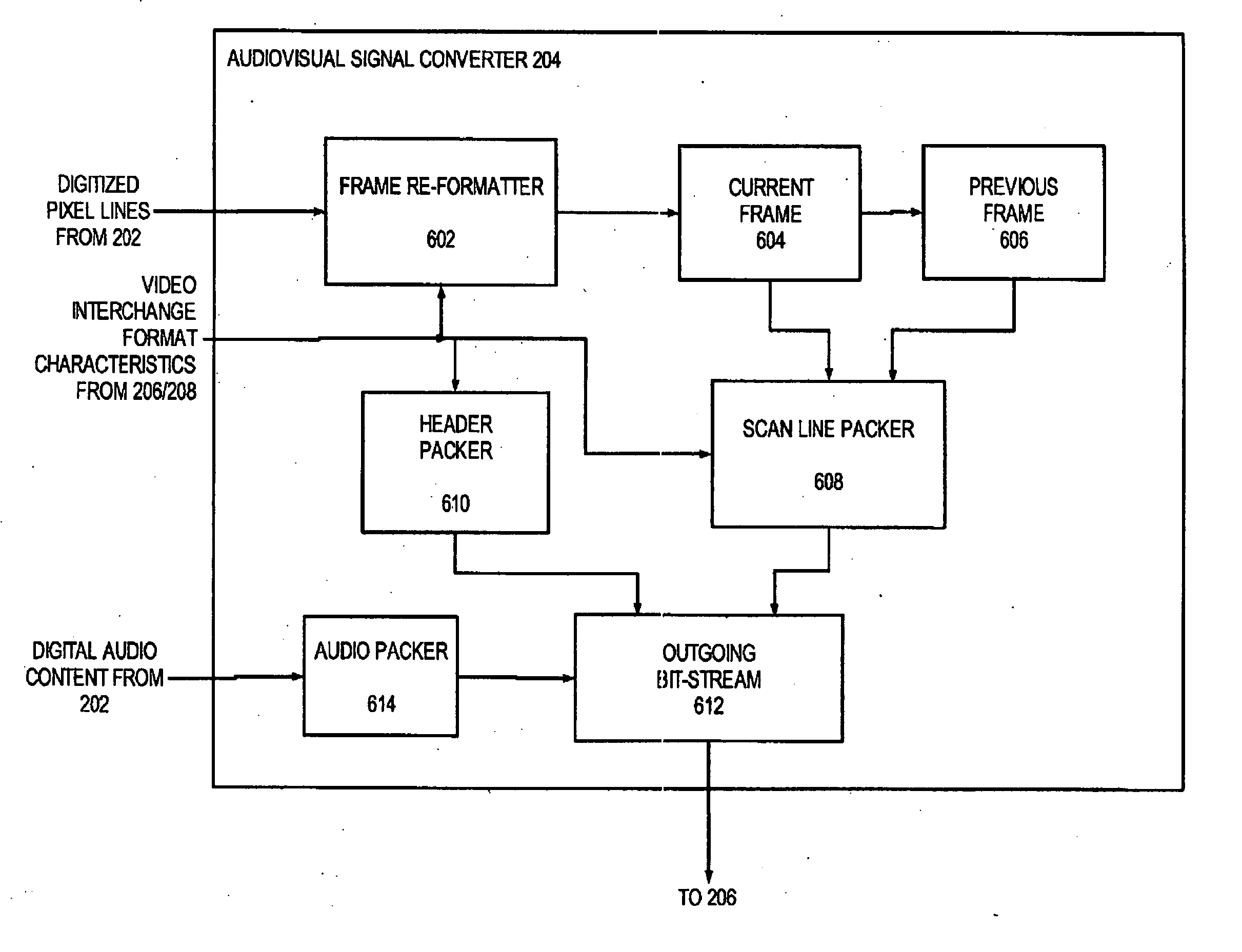
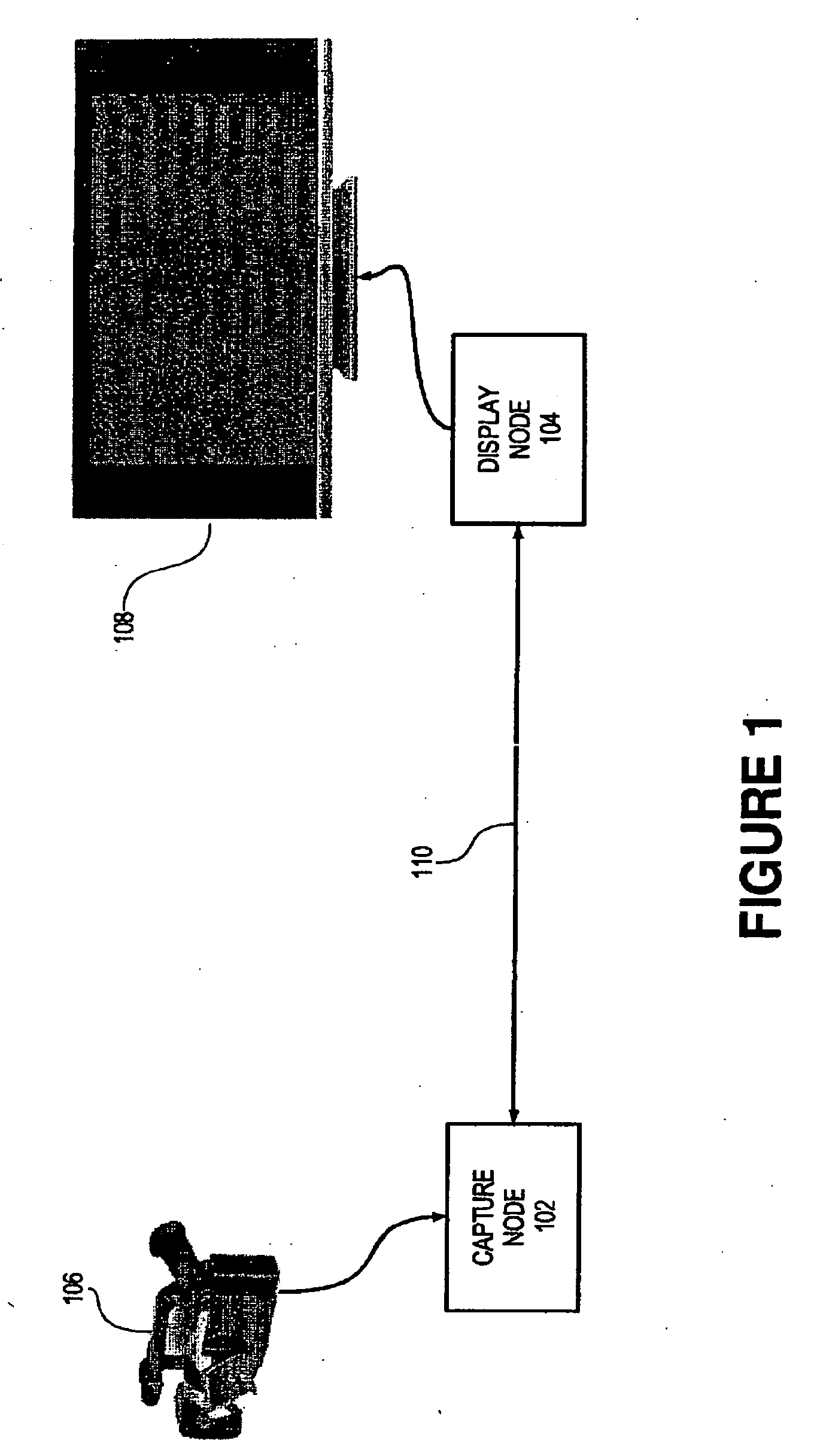
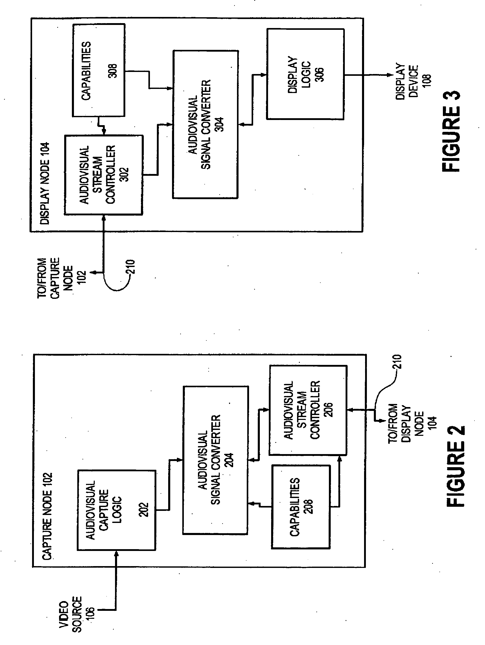
[0030] In accordance with the present invention, a capture node 102 (FIG. 1) and a display node 104 cooperate to transmit an audiovisual signal from a video source 106 to a display device 108 according to one or more digital audiovisual data formats, sometimes referred to herein as audiovisual interchange formats. Capture node 102 receives an audiovisual signal in a native format from source 106 and converts the audiovisual signal to a selected video interchange format for transmission to display node 104. Display node 104 receives the digital audiovisual signal in the selected video interchange format, converts the audiovisual signal to a displayable format supported by display device 108, and sends the audiovisual signal in the displayable format to display device 108.

[0031] As used herein, a “node” is any device or logic which can communicate through a network.

[0032] To facilitate appreciation and understanding of the following description, the various audiovisual signal format...


PUM


Abstract

An audiovisual signal is converted from a native format to a digital, packetized interchange format and transported between a capture node and a display node through a switch. The display node converts the audiovisual signal from the interchange format to a displayable format and causes display of the audiovisual signal. The use of a switch for video routing and distribution allows one-to-one, one-to-many, many-to-one, and many-to-many distribution. The use of a device-independent interchange format allows concurrent distribution of multiple heterogeneous audiovisual signals.

Description

CROSS-REFERENCE TO RELATED APPLICATIONS [0001] This Application is related to the following commonly-assigned and co-pending U.S. Patent Applications: (i) U.S. patent application Ser. No. 10 / ______ , entitled “A Display Node for Use in an Audiovisual Signal Routing and Distribution” (Attorney Docket P-2307 D2) and (ii) U.S. patent application Ser. No. 10 / ______, entitled “Audiovisual Signal Routing and Distribution System” (Attorney Docket P-2307 D3), both of which are filed on the same date as this Application and the teachings of which are incorporated herein by reference.FIELD OF THE INVENTION [0002] This invention relates to the field of audiovisual signal routing and distribution systems, and more specifically to a particularly efficient and flexible system for routing and distributing audiovisual signals of various differing formats. BACKGROUND [0003] A number of high-end video routing and distribution systems currently exist. One example is the Optima system of the AutoPatch™...

Claims


Application Information

Patent Timeline
IPC IPC(8): H04J3/16
CPCH04N5/46H04N7/01H04N21/4314H04N21/4621H04N21/440218H04N21/44227H04N21/4316
Inventor WOGSBERG, ERIC
Owner JUPITER SYST LLC
Why Eureka
Try Eureka