
A separate heating gas pressure calibration device with adjustable optical path

A technology for calibrating device and gas pressure, applied in the direction of measuring fluid pressure, measuring device, instrument, etc., can solve the problems of unreliable optical path system, inability to balance heating efficiency and device structure, etc., so as to solve the problem that heating efficiency and calibration device structure cannot be considered. , Adjustability expansion, the effect of reducing heat loss

Active Publication Date: 2022-03-25
BEIJING CHANGCHENG INST OF METROLOGY & MEASUREMENT AVIATION IND CORP OF CHINA
View PDF17 Cites 0 Cited by
  • Summary
  • Abstract
  • Description
  • Claims
  • Application Information

AI Technical Summary

Problems solved by technology

[0005] The object of the present invention is to provide a separate heating type gas pressure calibration device with adjustable optical path to solve the problems that the heating efficiency and device structure of the gas pressure calibration device based on optical measurement can not be balanced, and the optical path system is unreliable under high temperature and high pressure environment. In particular, it relates to a separate heating type gas pressure traceability device with adjustable optical path in high temperature and high pressure environment based on optical measurement such as laser interferometer

Method used


Image

  • A separate heating gas pressure calibration device with adjustable optical path
  • A separate heating gas pressure calibration device with adjustable optical path
  • A separate heating gas pressure calibration device with adjustable optical path

Examples


Embodiment Construction

[0023] The present invention will be further described in detail below in conjunction with the accompanying drawings and specific embodiments.

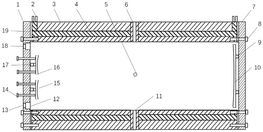
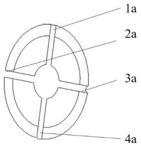
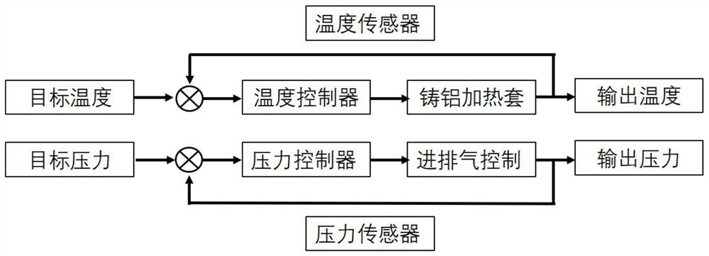
[0024] combine Figure 1~3 , a split heating gas pressure calibration device with adjustable optical path of the present invention includes: front cover 1, terminal block 2, cavity 3, built-in cast aluminum heating jacket 4, pressure sensor mounting hole 5, upper side temperature sensor Mounting hole 6, rear end cover 7, bolt 8, fixed support 9, first concave mirror 10, lower temperature sensor mounting hole 11, quartz glass 12, light inlet hole 13, adjustable screw 14, second concave mirror 15 , the third concave mirror 16 , the adjustable support 17 , the light exit hole 18 , and the sealing gasket 19 . The upper temperature sensor installation hole 1a, the pressure sensor installation hole 2a, the intake and exhaust holes 3a, and the lower temperature sensor installation hole 4a.

[0025] figure 1 It is the overall schematic dia...


PUM


Abstract

The invention relates to a split heating type gas pressure calibration device with adjustable optical path, which belongs to the field of measurement calibration. The heating of the gas medium inside the calibration device is realized by installing a cast aluminum heating jacket opposite to the cavity of the calibration device. The outer end surface of the cast aluminum heating jacket is flush with the end surface of the cavity, and the cast aluminum heating jacket and the outer end surface of the cavity are installed with sealing gaskets, and the end cover is fixed on the cavity by bolts. The first concave mirror is fixedly installed on the inner wall of the rear end cover, the second concave mirror and the third concave mirror are installed on the inner wall of the front end cover, and the attitude can be adjusted by adjusting the screw to ensure the adjustment of the optical path inside the calibration device. The temperature and pressure control system can not only realize the high-precision control of the temperature and pressure inside the cavity, but also ensure the uniformity of the temperature inside the cavity. The invention significantly improves the controllability of the temperature and pressure in the cavity, the timeliness and the stability of the optical path, and is suitable for pressure traceability based on optical measurement means in high temperature and high pressure environments.

Description

technical field [0001] The invention relates to a split heating type gas pressure calibration device with adjustable optical path, which belongs to the field of measurement calibration. Background technique [0002] The problem of traceable pressure measurement is the primary problem restricting the development of pressure measurement technology. Based on the refractive index or absorption spectrum, the direct measurement of pressure can be realized, which is an ideal traceable pressure measurement method. But for gas pressure measurement, both methods will face the outstanding problem of temperature change. Therefore, it is particularly important to conduct an in-depth analysis of the temperature effect in the gas pressure measurement based on the refractive index and absorption spectrum and to study the corresponding temperature compensation correction method. Designing a device that can simultaneously achieve high temperature and high pressure environments and is used f...

Claims


Application Information

Patent Timeline
Patent Type & Authority Patents(China)
IPC IPC(8): G01L27/00
CPCG01L27/005
Inventor 姜延欢杨军谢兴娟刘渊田森
Owner BEIJING CHANGCHENG INST OF METROLOGY & MEASUREMENT AVIATION IND CORP OF CHINA
Learn More