
Testing tool for testing rotation fluency of bearings with different sizes

A technology for testing tooling and fluency, applied in the field of bearing clamping, which can solve problems such as reducing the efficiency of bearing fluency testing

Inactive Publication Date: 2021-02-12
徐正涛
View PDF6 Cites 2 Cited by
  • Summary
  • Abstract
  • Description
  • Claims
  • Application Information

AI Technical Summary

Problems solved by technology

[0003] When testing the smoothness of bearing rotation, usually after the bearing is fixed, the inner ring of the bearing is rotated, and the smoothness of the bearing rotation is judged according to whether there is a certain resistance to the rotation of the inner ring. However, due to the different sizes of bearings on the market , so there are certain limitations in fixing bearings of different sizes when fixing the bearings, thus reducing the test efficiency of testing the bearing fluency

Method used


Image

  • Testing tool for testing rotation fluency of bearings with different sizes
  • Testing tool for testing rotation fluency of bearings with different sizes
  • Testing tool for testing rotation fluency of bearings with different sizes

Examples


Embodiment 1

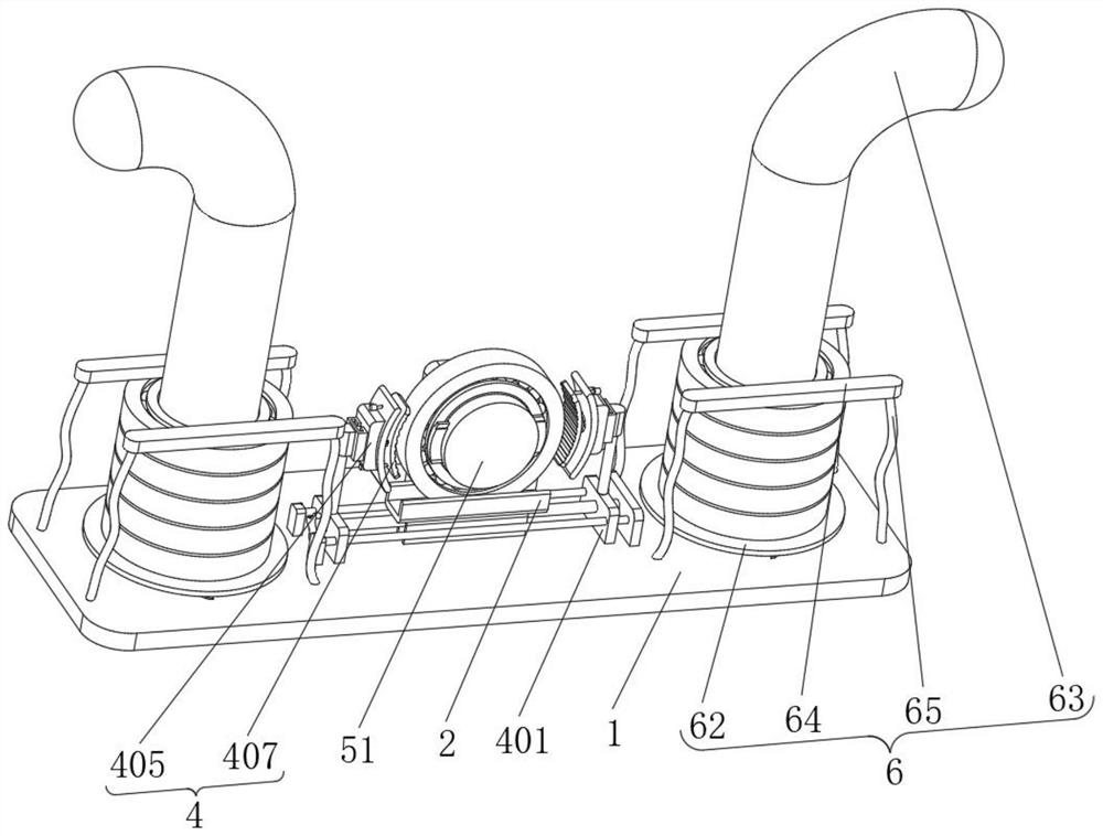
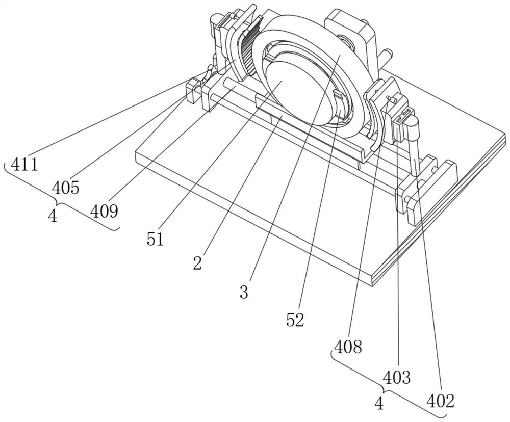
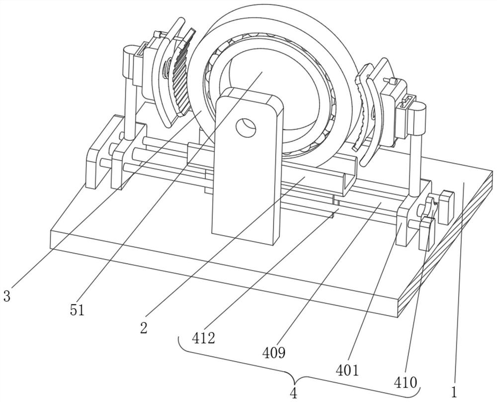
[0030] Example 1, such as Figure 1-8 As shown, the present invention provides a test tool for testing the smoothness of rotation of bearings of different sizes, including a backing plate 1 and a clamping device 4, a support plate 2 is fixedly installed on the upper surface of the backing plate 1, and the support plate 2 is away from One side of the backing plate 1 is slidingly connected with a bearing body 3 , the upper surface of the backing plate 1 is provided with a clamping device 4 , the inside of the bearing body 3 is provided with an auxiliary device 5 , and the upper surface of the backing plate 1 is provided with a storage device 6 .

[0031] The specific setting and function of the clamping device 4, the auxiliary device 5 and the storage device 6 will be described in detail below.

[0032] Such as image 3 with Figure 4 As shown, a support plate 2 is fixedly installed on the upper surface of the backing plate 1, and a bearing body 3 is slidably connected to the ...

Embodiment 2

[0038]Embodiment 2, on the basis of Embodiment 1, the storage device 6 includes a third spring 61, the lower end of the third spring 61 is fixedly connected to the backing plate 1, and the third spring 61 is evenly distributed on the surface of the backing plate 1, the third One end of the spring 61 away from the backing plate 1 is fixedly connected with a supporting plate 62, the supporting plate 62 is circular, and the inner wall of the supporting plate 62 is slidingly connected with a receiving rod 63, and the lower end of the receiving rod 63 is fixedly connected with the backing plate 1, and the receiving rod The upper end of 63 is arc-shaped, and the arc surface of receiving rod 63 is slidingly connected with pressing plate 64, and the two ends of pressing plate 64 are all fixedly connected with elastic cord 65, and the end of elastic cord 65 away from pressing plate 64 is fixedly connected with backing plate 1, the second The inside of the three springs 61 is slidingly c...


PUM


Abstract

The invention provides a testing tool for testing rotation fluency of bearings with different sizes, and relates to the technical field of bearing clamping; the testing tool comprises a backing plateand a clamping device, a support plate is fixedly mounted on the upper surface of the backing plate, and a bearing body is slidably connected to one side, away from the backing plate, of the support plate; the clamping device is arranged on the upper surface of the backing plate and comprises a sliding plate, the lower surface of the sliding plate is slidably connected with the backing plate, a connecting rod is fixedly connected to the side, away from the backing plate, of the sliding plate, a track plate is fixedly connected to the end, away from the sliding plate, of the connecting rod, anda sliding block is slidably connected to the inner wall of the track plate. A fixing block is fixedly connected to the side, away from the track plate, of the sliding block. According to the invention, the problem that the testing efficiency of testing the bearing smoothness is reduced due to the fact that the sizes of the bearings are different and the bearings with different sizes are limited to a certain extent when the bearings are fixed is solved.

Description

technical field [0001] The invention relates to the technical field of bearing clamping, in particular to a test tool for testing the smoothness of rotation of bearings of different sizes. Background technique [0002] Bearing is an important part of contemporary mechanical equipment. Its main function is to support the mechanical rotating body, reduce the friction coefficient during its movement, and ensure its rotation accuracy. The bearing usually determines its own size according to the applied mechanical size. Therefore, the bearings are diversified in size. [0003] When testing the smoothness of bearing rotation, usually after the bearing is fixed, the inner ring of the bearing is rotated, and the smoothness of the bearing rotation is judged according to whether there is a certain resistance to the rotation of the inner ring. However, due to the different sizes of bearings on the market , so when fixing the bearings, there are certain limitations in fixing bearings o...

Claims


Application Information

Patent Timeline
Patent Type & Authority Applications(China)
IPC IPC(8): G01M13/04
CPCG01M13/04
Inventor 徐正涛
Owner 徐正涛
Learn More