Constant velocity joint

A technology of constant velocity universal joints and universal joints, which is applied in the direction of elastic couplings, couplings, mechanical equipment, etc., can solve the problems of small opening angle increase rate and unfavorable ball cage, etc., and achieve reliable cage control Effect

Active Publication Date: 2021-02-12
GKN 动力传动系统国际有限责任公司
View PDF19 Cites 0 Cited by
  • Summary
  • Abstract
  • Description
  • Claims
  • Application Information

AI Technical Summary

Problems solved by technology

A track course with a large curvature or a large radius of curvature in the inner part of the joint leads to a relatively small increase in the opening angle when the joint is flexed, which can be disadvantageous for the control of the ball cage

Method used


Image

  • Constant velocity joint
  • Constant velocity joint
  • Constant velocity joint

Examples


Embodiment Construction

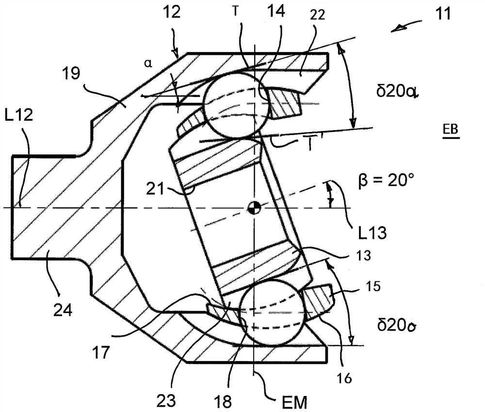
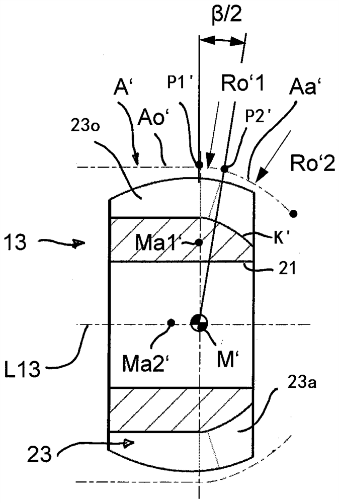
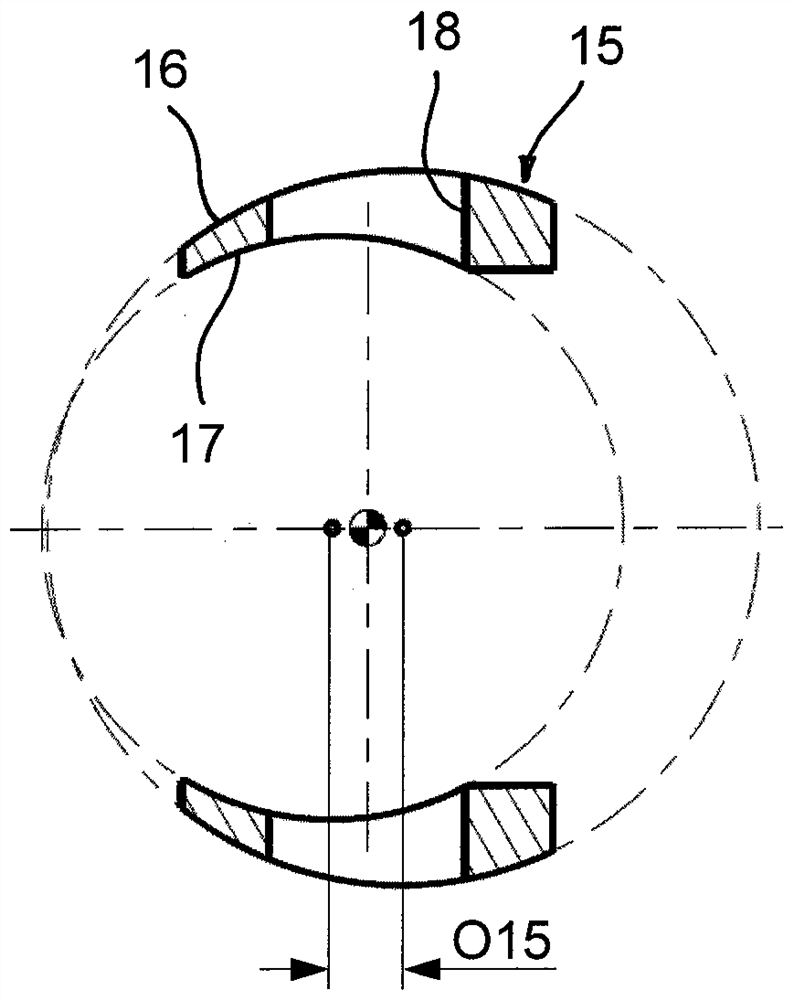
[0043] Commonly described below Figure 1A ) to 1G), Figure 2A ) to 2C) and image 3 . A constant velocity joint 11 according to the invention is shown. The constant velocity joint 11 includes a joint outer member 12 , a joint inner member 13 , balls 14 that transmit torque, and a ball cage 15 . The ball cage 15 has a spherical outer face 16 which is guided in the joint outer part 12 and a spherical cage inner face 17 which is guided on the joint inner part 13 . The balls 14 are held in the ball cage 15 in cage windows 18 distributed on the periphery in the joint center plane EM. The longitudinal axis L12 is marked at the joint outer part 12 and the longitudinal axis L13 at the joint inner part 13 . The point of intersection of the longitudinal axes L12, L13 and the joint center plane EM forms the center M of the joint.

[0044]The joint outer part 12 has a bottom 19 and an opening 20 to which a joint pin 24 is connected. The joint inner part 13 has an opening 21 into w...


PUM


Abstract

The invention relates to a constant velocity joint, comprising: a joint outer part (12) with outer ball tracks (22), a joint inner part (13) with inner ball tracks (23), wherein in each case one outerball track (22) and one inner ball track (23) form a track pair (22, 23) with one another; in each case one torque-transmitting ball (14) in each track pair (22, 23); a ball cage (15), in which the torque-transmitting balls (14) are received; wherein a first articulation angle range is defined which comprises articulation angles (beta) of less than twenty degrees, and a second articulation anglerange which comprises articulation angles (beta) of greater than twenty degrees; wherein a mouth opening angle (delta) increases within the first articulation angle range with an increasing articulation angle (beta), and wherein a first mean mouth opening angle rise (S1) of the first articulation angle range is greater than a second mean mouth opening angle rise (S2) of the second articulation angle range.

Description

technical field [0001] The invention relates to a constant velocity joint for torque transmission, which has: a joint outer part with an outer ball track; an inner joint part with an inner ball track; a torque transmission balls, which are guided in pairs of outer and inner ball tracks; and a ball cage (or ball cage, i.e. Kugelkaefig), which receives the balls in window holes distributed at the periphery And keep it in a common plane. Constant velocity joints enable torque transmission between the joint outer part and the joint inner part in the event of an angular movement. Background technique [0002] In principle, a distinction is made between constant velocity joints in the form of fixed joints and moving joints. In constant velocity fixed joints, essentially only angular mobility is provided between the joint outer part and the joint inner part, that is to say no axial movement is provided apart from the usual tolerances. In contrast to this, a constant-velocity joi...

Claims


Application Information

Patent Timeline
IPC IPC(8): F16D3/223F16D3/2237
CPCF16D3/223F16D3/2237F16D2003/22303F16D2003/22309Y10S464/906
Inventor I·本纳R·克雷梅柳斯A·格雷梅尔迈尔W·希尔德布兰特S·毛赫尔H-J·波斯特T·韦克林
Owner GKN 动力传动系统国际有限责任公司
Why Eureka
Try Eureka