
Automatic pin hole centering detection device and pin hole reference line manufacturing device

An automatic detection device and technology of the detection device are applied in the directions of measuring devices, mechanical measuring devices, and optical devices, etc., and can solve the problems of difficulty in centering the locking pin and the locking hole, etc.

Active Publication Date: 2021-02-19
SANY ELECTRIC CO LTD
View PDF7 Cites 0 Cited by
  • Summary
  • Abstract
  • Description
  • Claims
  • Application Information

AI Technical Summary

Problems solved by technology

[0004] The purpose of the present invention is to provide an automatic detection device for pin hole centering and a manufacturing device for pin hole reference lines, so as to alleviate the technical problem of the difficulty in centering the locking pin and the locking hole in the related art

Method used


Image

  • Automatic pin hole centering detection device and pin hole reference line manufacturing device
  • Automatic pin hole centering detection device and pin hole reference line manufacturing device
  • Automatic pin hole centering detection device and pin hole reference line manufacturing device

Examples


Embodiment Construction

[0044] The technical solutions of the present invention will be clearly and completely described below in conjunction with the accompanying drawings. Apparently, the described embodiments are some of the embodiments of the present invention, but not all of them. Based on the embodiments of the present invention, all other embodiments obtained by persons of ordinary skill in the art without making creative efforts belong to the protection scope of the present invention.

[0045] In the description of the present invention, it should be noted that the terms "center", "upper", "lower", "left", "right", "vertical", "horizontal", "inner", "outer" etc. The indicated orientation or positional relationship is based on the orientation or positional relationship shown in the drawings, and is only for the convenience of describing the present invention and simplifying the description, rather than indicating or implying that the referred device or element must have a specific orientation, ...


PUM


Abstract

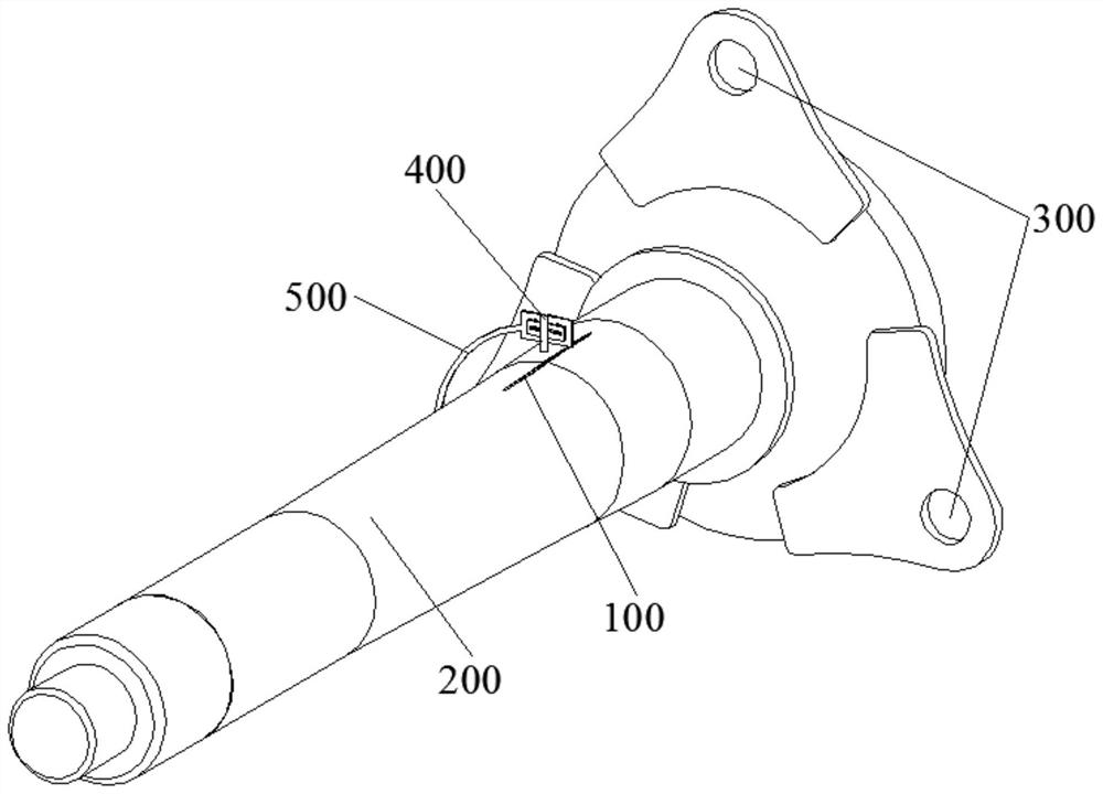
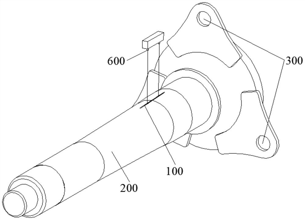
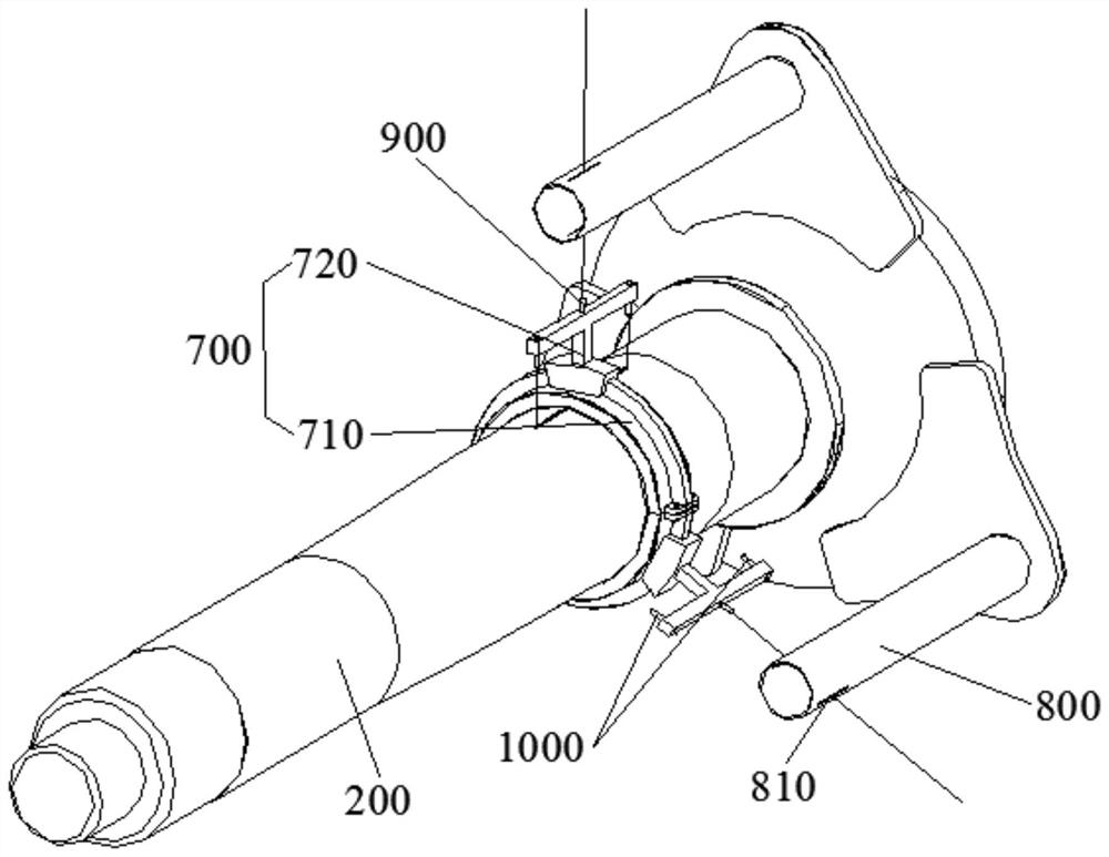
The invention provides an automatic pin hole centering detection device and a pin hole reference line manufacturing device, and relates to the technical field of wind power generation systems. The automatic pin hole centering detection device comprises the pin hole reference line and a detection device, and the pin hole reference line is arranged on the circumferential surface of a main shaft; thepin hole reference line, the axis of the main shaft, and the axis of the locking hole are located in the same plane. The detection device is arranged at the fixed position close to the circumferential surface of the main shaft, is located on the same plane as the locking pin and is used for detecting the pin hole reference line, and when the detection device detects the pin hole reference line, an operator can obtain information that the locking pin and the locking hole are centered from the detection device. The technical problem that a locking pin and a locking hole are difficult to centerin the prior art is solved, the working efficiency is improved, and manpower is saved.

Description

technical field [0001] The invention relates to the technical field of wind power generation systems, in particular to an automatic detection device for pin hole centering and a manufacturing device for a pin hole reference line. Background technique [0002] At present, during the cranking process, it is difficult to align the pin hole of the wind wheel locking disc with the locking pin of the wind wheel, and it is impossible to smoothly insert the locking pin into the pin hole of the locking disc. In the existing technical solution, more operators are required for the alignment of the locking pin and the pin hole, and the operators observe the positions of the locking pin and the pin hole with naked eyes, and then realize the alignment. This alignment method has low precision, and requires repeated corrections in the operation process, and the efficiency is also low, and requires the operator to have certain work experience, otherwise it cannot be competent for the work. ...

Claims


Application Information

Patent Timeline
IPC IPC(8): G01B11/00G01B11/27
CPCG01B11/00G01B11/27G01B5/0004
Inventor 石胜杰
Owner SANY ELECTRIC CO LTD
Learn More