Automatic state detection device and method for railway track spring bar fastener

An automatic detection device and technology for railway tracks, which are applied in the directions of tracks, track maintenance, roads, etc., can solve problems such as difficulties, lack of devices or equipment for railway track fastener detection, time-consuming and labor-intensive, etc.

Active Publication Date: 2016-12-07
WUHAN HANNING TECH +1
View PDF5 Cites 29 Cited by
  • Summary
  • Abstract
  • Description
  • Claims
  • Application Information

AI Technical Summary

Problems solved by technology

[0002] With the development of the transportation industry, the development of rail transit is becoming more and more rapid; in the railway track, many different railway track fasteners will be applied to assist in the installation, fixing and connection between the tracks, among which the elastic buckle Fasteners are very common fasteners; in order to ensure the safety of rail transit, it is necessary to check railway track fasteners along the road. In the prior art, the inspection of railway track fasteners is still in the stage of manual operation, and railway The inspection of rail fasteners mainly includes: checking whether there is looseness and cracks, and whether there is looseness can be detected by maintenance personnel using tools, but it is difficult to manually judge whether there are cracks in fasteners; and because railways often It will stretch for dozens of kilometers, and the environment in which it is located is sometimes relatively harsh. If only manual maintenance is used, there will be defects such as huge labor, time-consuming and labor-intensive
[0003] At present, there is no device or equipment that can automatically detect railway track fasteners in this field and in the prior art of similar technical fields.

Method used


Image

  • Automatic state detection device and method for railway track spring bar fastener
  • Automatic state detection device and method for railway track spring bar fastener

Examples


Embodiment 2

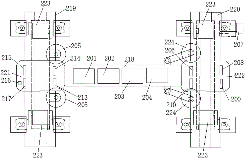
[0082] like figure 2 In the second embodiment shown, in the automatic detection device for the state of the rail clip fastener in this embodiment, the running mechanism includes: a patrol trolley;

[0083]The patrol trolley includes: a car body, the car body includes: a crossbeam 218, a left longitudinal beam 219, a right longitudinal beam 220 and at least four traveling wheels 223, the traveling wheels 223 are in close contact with the top surface of the rail to prevent the car body from bumping up and down , the above-mentioned car body is also provided with a positioning wheel 205 and a tensioning wheel 224, wherein the positioning wheel 205 is always close to the inner surface of the rail; the tensioning wheel 224 adjusts the degree of tension as the gauge of the track changes to avoid The body shakes left and right; the central positions of the above-mentioned left longitudinal beam 219 and right longitudinal beam 220 are respectively connected with the left and right en...


PUM


Abstract

The invention provides an automatic state detection device and method for a railway track spring bar fastener. The device comprises a travelling mechanism; a travelling control mechanism is connected to the travelling mechanism; a spring bar fastener distance measurement module, an image acquisition module, a spring bar fastener surface three-dimensional point cloud acquisition module, and a data processing and judging module are fixedly mounted on the travelling mechanism; the spring bar fastener surface three-dimensional point cloud acquisition module is used for acquiring integral three-dimensional point cloud data of the spring bar fastener; the travelling control mechanism comprises a wireless receiver, a microprocessor and a driving motor; the data processing and judging module is used for determining the edge of a fastener in a spring bar fastener plane image based on the three-dimensional point cloud data and image data, extracting the image of the spring bar fastener, and judging whether a crack exists on the spring bar fastener according to the extracted image of the spring bar fastener. According to the automatic state detection device and method, whether the crack exists on the spring bar fastener or not can be detected automatically.

Description

technical field [0001] The invention relates to the technical field of rail detection, in particular to an automatic detection device and method for the state of rail clip fasteners. Background technique [0002] With the development of the transportation industry, the development of rail transit is becoming more and more rapid; in the railway track, many different railway track fasteners will be applied to assist in the installation, fixing and connection between the tracks, among which the elastic buckle Fasteners are very common fasteners; in order to ensure the safety of rail transit, it is necessary to check railway track fasteners along the road. In the prior art, the inspection of railway track fasteners is still in the stage of manual operation, and railway The inspection of rail fasteners mainly includes: checking whether there is looseness and cracks, and whether there is looseness can be detected by maintenance personnel using tools, but it is difficult to manuall...

Claims


Application Information

Patent Timeline
Patent Type & Authority Applications(China)
IPC IPC(8): E01B35/00
CPCE01B35/00
Inventor 毛庆洲郑继忠李志明毛庆乐
Owner WUHAN HANNING TECH
Why Eureka
Try Eureka