Calibration method and device based on machine vision

A technology of machine vision and calibration method, applied in instruments, computer parts, image data processing, etc., can solve problems such as inability to identify, and achieve the effect of solving occlusion

Pending Publication Date: 2021-02-19
北京大华旺达科技有限公司
View PDF0 Cites 0 Cited by
  • Summary
  • Abstract
  • Description
  • Claims
  • Application Information

AI Technical Summary

Problems solved by technology

[0003] The technical problem to be solved by the present invention is to provide a calibration method and device based on machine vision, which can effectively prevent unrecognizable and inaccurate recognition problems caused by occlusion and poor angles

Method used


Image

  • Calibration method and device based on machine vision
  • Calibration method and device based on machine vision
  • Calibration method and device based on machine vision

Examples


Embodiment Construction

[0029] The preferred embodiments of the present invention will be described below in conjunction with the accompanying drawings. It should be understood that the preferred embodiments described here are only used to illustrate and explain the present invention, and are not intended to limit the present invention.

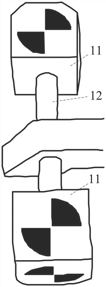
[0030] The invention relates to the identification and position reconstruction of marking points of machine vision. Aiming at the problem that the position and angle of the marker point in the binocular camera have a significant impact on the recognition and reconstruction of the marker point, the present invention proposes a three-dimensional marker block structure: between two cubes 11 with known spatial poses, a Connecting rods 12 are connected, and features such as X corner points are distributed on the remaining 10 surfaces. At different angles, more than two X corner points can be identified. According to the position and direction of the corner point on the ...


PUM


Abstract

The invention provides a calibration method and device based on machine vision. The method comprises the following steps of: starting from a first surface of a mark point template, finding out a pointin three-dimensional coordinates, which satisfies a congruent triangle and a relative direction relationship with a space coordinate of the surface, by using an exhaustion method; performing SVD (singular value decomposition) on the three found points and template point coordinates, and solving a rotation matrix and a translation vector of the mark points in the camera; and projecting all pointsin the template to a camera coordinate system by using the rotation matrix and the translation vector to obtain a group of theoretical three-dimensional coordinates, comparing the theoretical three-dimensional coordinates with the three-dimensional coordinates for identifying the X corner points, screening through distance and direction constraints, and picking out the points belonging to the markpoints. According to the calibration method and device based on machine vision provided by the invention, the problems of unrecognizable and inaccurate recognition caused by shielding and poor angleare effectively prevented.

Description

technical field [0001] The invention relates to the technical field of machine vision, in particular to a calibration method and device based on machine vision. Background technique [0002] As we all know, the occlusion problem is a very difficult problem in binocular vision tracking in machine vision. In the process of using binocular vision, the recognition effect is often poor or even fails due to problems such as occlusion and inappropriate angles. Users often have to In order to take care of the recognition effect of the binocular camera, the pose of the marker points can be adjusted randomly, which will cause a large obstacle to use. Contents of the invention [0003] The technical problem to be solved by the present invention is to provide a calibration method and device based on machine vision, which can effectively prevent the problems of unrecognizable and inaccurate recognition caused by occlusion and poor angle. [0004] In order to solve the above technical ...

Claims


Application Information

Patent Timeline
Patent Type & Authority Applications(China)
IPC IPC(8): G06T7/70G06K9/00
CPCG06T7/70G06T2207/20164G06V20/10Y02T10/40
Inventor 胡宁张小娟
Owner 北京大华旺达科技有限公司
Why Eureka
Try Eureka