Combined relay with high stability

A high stability, relay technology, applied in the direction of relays, electromagnetic relays, electromagnetic relay details, etc., can solve the poor stability of combined relays, the difficulty of disassembling and separating the combined relay and the outer cover, and the poor installation and fixing effect of the combined relay and the base and other issues to achieve high stability

Inactive Publication Date: 2021-02-19
西安鼎腾电子科技有限公司
View PDF2 Cites 6 Cited by
  • Summary
  • Abstract
  • Description
  • Claims
  • Application Information

AI Technical Summary

Problems solved by technology

[0007] The purpose of the present invention is to solve the problems in the prior art that the installation and fixing effect of the combined relay and the base is poor, making the stability of the combined relay poor, and the combined relay and the outer cover are difficult to disassemble and separate, and a proposed High stability combined relay

Method used


Image

  • Combined relay with high stability
  • Combined relay with high stability

Examples


Embodiment 1

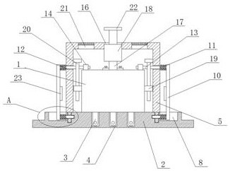
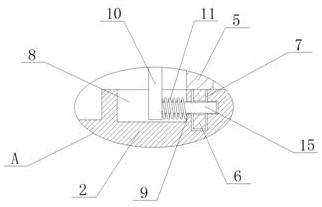
[0023] Example 1, such as Figure 1-2 , this high-stability combined relay includes a relay body 1 and a base 2. The bottom of the relay body 1 is rectangular and equidistantly installed with several pins 3. The base 2 is arranged under the relay body 1. The base 2 The upper end is provided with a jack 4 matching the pin 3, the relay body 1 is provided with a cover 5, and the bottom of the cover 5 is fixedly connected with a fixed frame 6 symmetrically, and a fixed groove 7 is provided on the base 2 below the fixed frame 6. The upper end of the base 2 is symmetrically provided with a movable groove 8, and the wall of the fixed groove 7 is provided with a fixed hole 9 and a positioning groove, and both sides of the outer cover 5 are provided with a movable plate 10, and the movable plate 10 is symmetrically fixedly connected with a spring 11, a spring 11 The other end of the relay body is fixedly connected to the outer side wall of the outer cover 5 or the groove wall of the mo...

Embodiment 2

[0024] Embodiment 2 is on the basis of embodiment 1 such as figure 1 As shown, both sides of its relay body 1 are symmetrically fixedly connected with slip rings 19, and inside the outer cover 5 are symmetrically fixedly connected with T-shaped sliding rods 20. The position limit prevents the relay body 1 from sliding in the horizontal direction.

Embodiment 3

[0025] Embodiment 3 is such as on the basis of embodiment 1 figure 1 As shown, the wall of the push rod 17 is fixedly sleeved with a flange, and the push rod 17 is connected with the relay body 1 through screws and the flange, which facilitates the installation and disassembly of the push rod 17 and the relay body 1 .


PUM


Abstract

The invention relates to the technical field of relays, and discloses a combined relay with high stability, which comprises a relay body and a base, a plurality of pins are uniformly and equidistantlyarranged at the bottom of the relay body in a rectangular shape, the base is arranged below the relay body, and jacks matched with the pins are formed in the upper end of the base. The relay body issleeved with an outer cover, the bottom of the outer cover is symmetrically and fixedly connected with a fixed frame, a fixed groove is formed in the base located below the fixed frame, movable grooves are symmetrically formed in the upper end of the base, fixed holes and positioning grooves are formed in the groove walls of the fixed grooves, and movable plates are arranged on the two sides of the outer cover. The combined relay is stably installed in the outer cover and on the base, the stability of the combined relay is improved, the combined relay can be detached and separated from the outer cover and the base at the same time, and the combined relay can be conveniently taken out to be maintained or replaced.

Description

technical field [0001] The invention relates to the technical field of relays, in particular to a high-stability combined relay. Background technique [0002] When the relay is in use, it is generally composed of a relay and a relay base. The relay base can be quickly installed on the guide rail, and can lead the coil of the relay and the contact of the electric shock to the quick connection column of the base, so that when using and wiring It is very convenient. If the relay is damaged, the relay can be pulled out from the base and replaced directly, saving maintenance time. [0003] The existing patent (announcement) No. CN207587637U discloses a combined relay, which can not only prevent the relay from shaking, but also facilitate the maintenance and replacement of the relay; [0004] The existing patent (announcement) No. CN208738142U discloses a combined relay, the design of the limit block, the effect is that the limit block can reduce the gap between the iron core and...

Claims


Application Information

Patent Timeline
Patent Type & Authority Applications(China)
IPC IPC(8): H01H50/04
CPCH01H50/042H01H50/048
Inventor 宋鹏飞
Owner 西安鼎腾电子科技有限公司
Why Eureka
Try Eureka