Steel structure clamping and fixing device capable of manually adjusting clamping angle

A manual adjustment, clamping and fixing technology, applied in the field of steel structures, can solve problems such as troublesome operation, affecting work efficiency, and inconvenient use

Inactive Publication Date: 2021-02-23
李殿华
View PDF0 Cites 1 Cited by
  • Summary
  • Abstract
  • Description
  • Claims
  • Application Information

AI Technical Summary

Problems solved by technology

[0003] In the process of manufacturing steel structures, they are usually polished and cut in various ways. When processing them, in order to ensure the stability of the processing, they need to be fixed. Due to the many processing procedures and the angle of processing , needs to be changed at any time, so when fixing the steel structure, it needs to be repeatedly installed and disassembled, which makes the operation troublesome, inconvenient to use, and affects the efficiency of the work, and the existing steel structure fixing device is stable when clamping and fixing. sexual insufficiency

Method used


Image

  • Steel structure clamping and fixing device capable of manually adjusting clamping angle
  • Steel structure clamping and fixing device capable of manually adjusting clamping angle
  • Steel structure clamping and fixing device capable of manually adjusting clamping angle

Examples


Embodiment 1

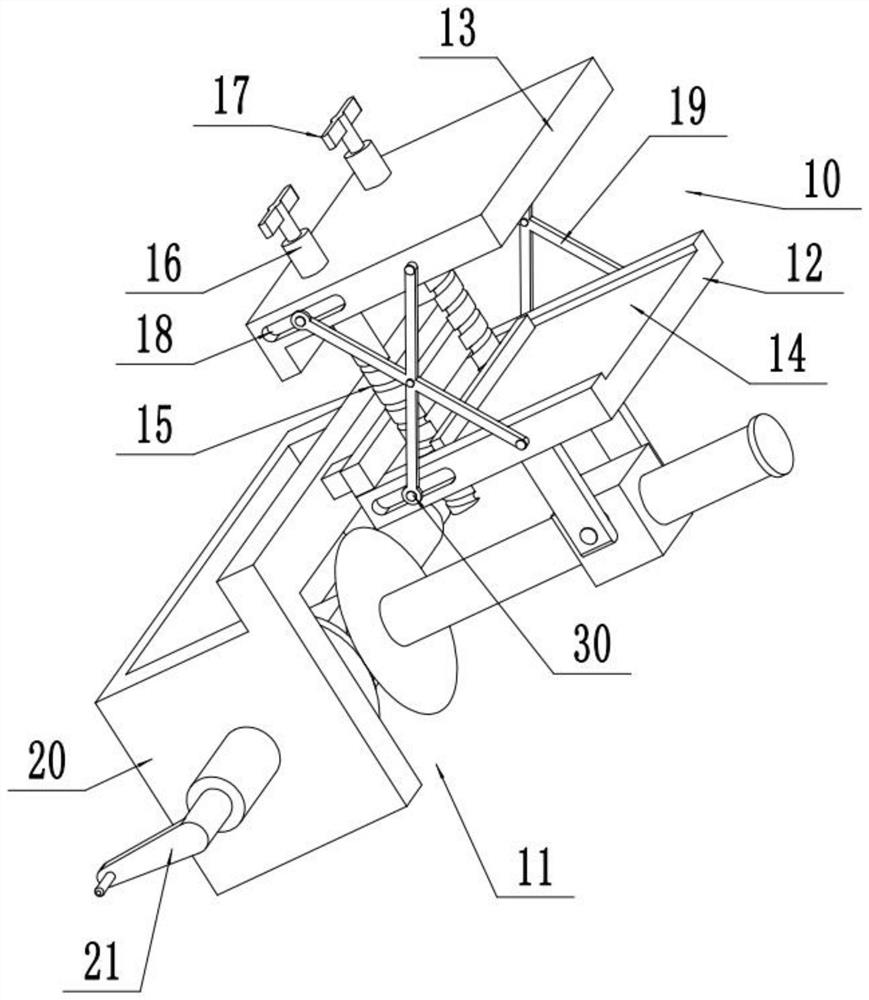
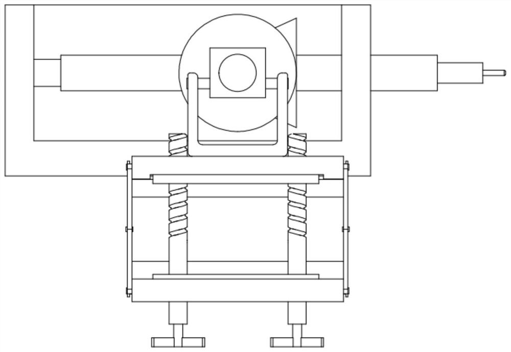
[0019] see Figure 1-4 , a steel structure clamping and fixing device that can manually adjust the clamping angle, including a clamping mechanism 10, an adjusting mechanism 11, a fixed splint 12, and a movable splint 13; the clamping mechanism 10 includes two sets of opposite fixed splints 12 and The movable splint 13, the lower part of the front and rear side walls of the fixed splint 12 and the movable splint 13 are provided with a waist-shaped chute 18, and the inside of the chute 18 is slidably connected with a slider 30, and the left and right side walls of the fixed splint 12 and the movable splint 13 are respectively The two groups of connecting rods 19 connected by the middle part are connected, and the bottom ends of the connecting rods 19 are respectively connected to the sliders 30 inside the two groups of chute 18, and the top ends of the connecting rods 19 are connected to the fixed splint 12 and the movable splint 13. On the side wall, the fixed splint 12 and the...

Embodiment 2

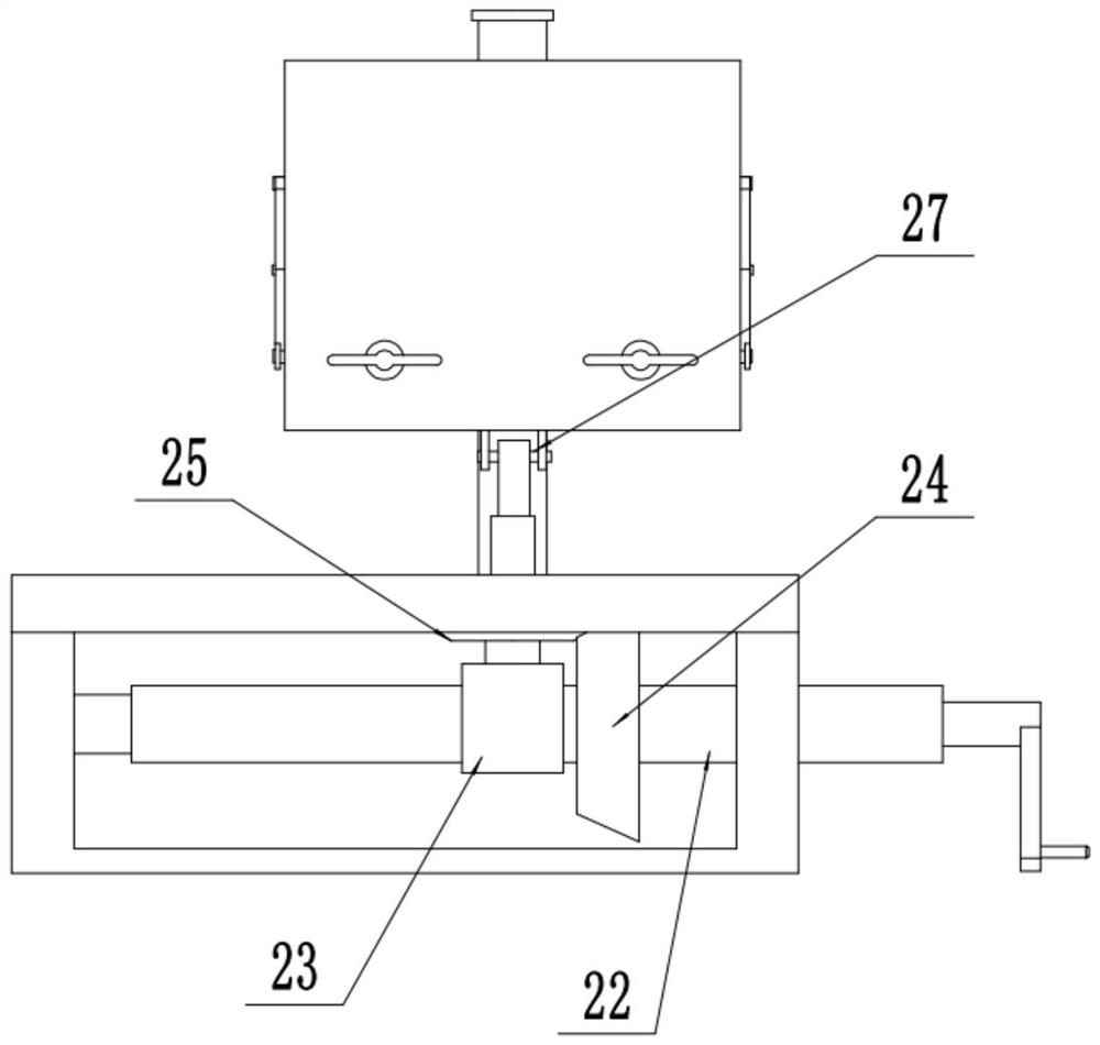
[0023] refer to Figure 5 , on the basis of Embodiment 1, baffles 31 are symmetrically installed on the inner sides of the fixed splint 12 and the movable splint 13, which are close to the clamping groove 14, and the baffles 31 are set to block the steel structure during clamping. Touch the adjustment screw-15 and other parts. Two groups of fastening plates 32 are arranged symmetrically on the front and rear sides of the inside of the clamping groove 14, rubber pads are fixedly installed on the opposite sides of the fastening plates 32, and an adjusting screw 2 33 is fixedly installed on the middle of the outer side of the fastening plate 32. Adjusting screw 2 33 is threadedly connected with internal thread groove 35 provided in clamping groove 14, and the outer end of adjusting screw 2 33 is fixedly equipped with rotating handle 3 34, and two groups of fastening plates 32 are approached by rotating rotating handle 3 34 , so that it can be used for steel structures of differe...


PUM


Abstract

The invention relates to the technical field of steel structures, and discloses a steel structure clamping and fixing device capable of manually adjusting a clamping angle. The steel structure clamping and fixing device capable of manually adjusting the clamping angle comprises a clamping mechanism, an adjusting mechanism, a fixed clamping plate and a movable clamping plate. The clamping mechanismcomprises the fixed clamping plate and the movable clamping plate which are opposite, the left side walls and the right side walls of the fixed clamping plate and the movable clamping plate are connected through two sets of connecting rods with the middles rotationally connected, the bottom ends of the connecting rods are rotationally connected to sliding blocks in two sets of sliding grooves correspondingly, two first adjusting screws are in threaded connection with the interiors of the front and rear lower sides of the fixed clamping plate, and the left ends of the first adjusting screws are fixedly connected with a set of connecting rods with the left ends movably penetrating through the movable clamping plate. The adjusting mechanism is arranged on the right side of the lower portionof the clamping mechanism and comprises an adjusting base of a frame structure, and a supporting block fixed to the left side of the top of the adjusting base is rotationally connected to the bottom middle portion of the fixed clamping plate through a U-shaped supporting block.

Description

technical field [0001] The invention relates to the technical field of steel structures, in particular to a steel structure clamping and fixing device that can manually adjust the clamping angle. Background technique [0002] Steel structure is a structure composed of steel materials. It is one of the main types of building structures. Chemical, washing and drying, galvanizing and other rust removal and anti-rust processes. The components or components are usually connected by welds, bolts or rivets. [0003] In the process of manufacturing steel structures, it is usually polished and cut in various ways. When processing it, in order to ensure the stability of the processing, it needs to be fixed. Due to the many processing procedures and the angle of processing , needs to be changed at any time, so when fixing the steel structure, it needs to be repeatedly installed and disassembled, which makes the operation troublesome, inconvenient to use, and affects the efficiency of...

Claims


Application Information

Patent Timeline
Patent Type & Authority Applications(China)
IPC IPC(8): B23Q3/06B24B41/06
CPCB23Q3/062B24B41/06
Inventor 李殿华
Owner 李殿华
Why Eureka
Try Eureka