Energy-saving vehicle-mounted air purification device for new energy automobile

An air purification device and new energy vehicle technology, which is applied in air treatment equipment, vehicle parts, transportation and packaging, etc., can solve the problem of inconvenient power supply for vehicle-mounted air purifiers, and achieve good air purification effects

Inactive Publication Date: 2021-02-23
方飞
View PDF0 Cites 5 Cited by
  • Summary
  • Abstract
  • Description
  • Claims
  • Application Information

AI Technical Summary

Problems solved by technology

[0005] The object of the present invention is to provide an energy-saving and environment-friendly energy-saving vehicle-mounted air-purifying device for new energy vehicles to solve the problem of inconvenient power supply of the above-mentioned vehicle-mounted air purifier.

Method used


Image

  • Energy-saving vehicle-mounted air purification device for new energy automobile
  • Energy-saving vehicle-mounted air purification device for new energy automobile
  • Energy-saving vehicle-mounted air purification device for new energy automobile

Examples


Embodiment 1

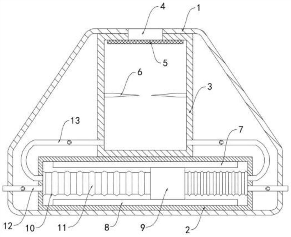
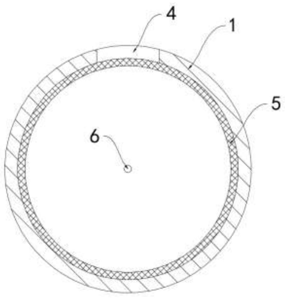
[0022] Such as Figure 1-2 As shown, an energy-saving vehicle-mounted air purification device for new energy vehicles includes a housing 1, an air intake cylinder 2 and a purification box 3 are arranged in the housing 1, the air intake cylinder 2 is fixedly installed on the inner bottom surface of the housing 1, and the purification box 3 is fixedly connected to the inner top surface of the housing 1, the top surface of the housing 1 is provided with an exhaust hole 4 communicating with the purification box 3, and a dust filter 5 is installed in the purification box 3, and the side walls on both sides of the purification box 3 Discharge needles 6 are fixedly installed respectively, and the tips of the two discharge needles 6 are facing each other without touching each other.

[0023] The upper and lower friction plates 7 and 8 are respectively fixedly connected to the top surface and the bottom surface of the intake cylinder 2, the upper friction plate 7 is a glass plate, the ...

Embodiment 2

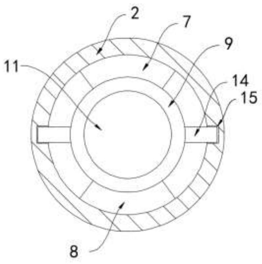
[0029] Such as image 3 As shown, the difference between the present embodiment and the first embodiment is that the dust filter 5 is arranged in a cylindrical shape and is rotatably connected with the inner wall of the purification box 3 .

[0030] In this embodiment, the air in the purification box 3 gathers upwards, passes through the dust filter 5 and is discharged from the exhaust hole 4, and a large amount of dust and impurities are attached to the upper half of the dust filter 5, and the weight increases. The net 5 rolls in the purification box 3, the part with a large amount of dust and impurities is rotated to the bottom, and the unused part is rotated to the upper exhaust hole 4, which is convenient for the uniform consumption and full utilization of the dust filter net 5.


PUM


Abstract

The invention belongs to the technical field of new energy vehicles, and particularly relates to an energy-saving vehicle-mounted air purification device for a new energy vehicle. The device comprisesa shell, an air inlet cylinder and a purification box are arranged in the shell, the air inlet cylinder is fixedly arranged on the inner bottom surface of the shell, and the purification box is fixedly connected to the inner top surface of the shell; an exhaust hole communicated with the purification box is formed in the top face of the shell, a dust filtering net is installed in the purificationbox, spray points are fixedly installed on the side walls of the two sides of the purification box respectively, the tip ends of the two spray points are right opposite and do not make contact with each other, and the top face and the bottom face of the air inlet cylinder are fixedly connected with an upper friction plate and a lower friction plate respectively. A balancing weight can slide backand forth in the air inlet cylinder under the inertia effect to suck air in a vehicle, dust and impurities in the air are filtered out through a dust filtering net, a good air purification effect is achieved, air discharge is broken down through the spray points, air negative ions are generated, and the purposes of cleaning and purifying the air are further achieved.

Description

technical field [0001] The invention belongs to the technical field of new energy vehicles, and in particular relates to an energy-saving vehicle-mounted air purification device for new energy vehicles. Background technique [0002] New energy vehicles are vehicles that use unconventional vehicle fuel as a power source, which is of great significance to the protection of energy and the environment. With the acceleration of industrialization, air pollution is becoming more and more serious. New energy vehicles are often equipped with air purification devices to Improve the air quality inside the car and provide drivers with a good driving environment. [0003] The traditional car air purifier is inconvenient to supply power. It is powered by a rechargeable battery or directly from the car battery of a new energy vehicle. The rechargeable battery needs to be charged regularly and the battery has a certain service life. Air purification will not be achieved when the battery is...

Claims


Application Information

Patent Timeline
Patent Type & Authority Applications(China)
IPC IPC(8): B60H3/00B60H3/06
CPCB60H3/0078B60H3/06
Inventor 方飞李俊玲
Owner 方飞
Why Eureka
Try Eureka