
Gas turbine electromagnetic valve control vent valve

A technology for gas turbines and solenoid valves, applied to combustion engines, internal combustion piston engines, valve operating/release devices, etc., can solve the problems of high structural complexity, low maturity, and high cost of vent valves, and avoid high costs , The effect of simple deflation structure

Active Publication Date: 2021-02-23
AECC SHENYANG ENGINE RES INST
View PDF6 Cites 0 Cited by
  • Summary
  • Abstract
  • Description
  • Claims
  • Application Information

AI Technical Summary

Problems solved by technology

Mechanical bleed valves can usually be divided into two categories. One type does not depend on external air sources. The bleed valve is controlled by the internal air pressure of the engine, but it is difficult to realize the quick opening and slow closing functions of the valve, and the consistency of the valve action is poor; The second type requires an external air source to bleed air. By changing the pressure of the external air source, the pressure of the upper and lower chambers of the valve core is adjusted to realize the control of the valve's instant opening and slow closing.
Solenoid valve-controlled bleed valve can satisfy valve instant opening and slow closing control, but compared with pure mechanical bleed valve, its structure is more The valve, the valve is located in a high temperature environment, the solenoid valve control structure in the air release valve needs to have high temperature resistance, and needs special research and development, the cost of the entire air release valve is high, and the maturity is low

Method used


Image

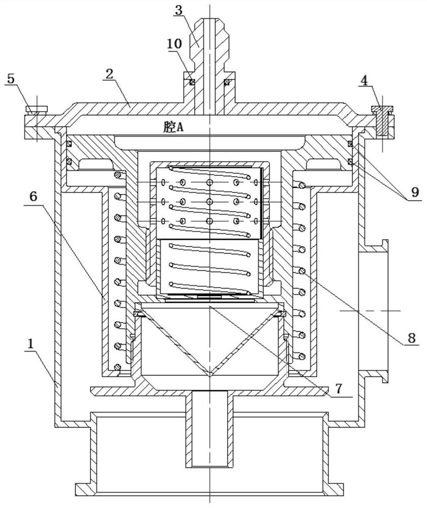
  • Gas turbine electromagnetic valve control vent valve
  • Gas turbine electromagnetic valve control vent valve
  • Gas turbine electromagnetic valve control vent valve

Examples


Embodiment Construction

[0038] In order to make the purpose, technical solution and advantages of the application more clear, the technical solution in the embodiment of the application will be described in more detail below in conjunction with the drawings in the embodiment of the application. In the drawings, the same or similar reference numerals denote the same or similar elements or elements having the same or similar functions throughout. The described embodiments are some, but not all, embodiments of the application. The embodiments described below by referring to the figures are exemplary, and are intended to explain the present application, and should not be construed as limiting the present application. Based on the embodiments in this application, all other embodiments obtained by persons of ordinary skill in the art without creative efforts fall within the protection scope of this application. Embodiments of the present application will be described in detail below in conjunction with th...


PUM


Abstract

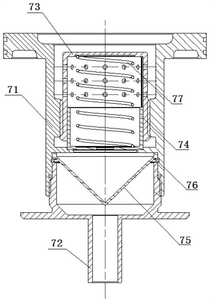
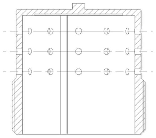
The invention belongs to the field of fuel control systems, and particularly relates to a gas turbine electromagnetic valve control vent valve. The valve comprises a shell 1, an end cover 2, a controlconnector 3, a main spring seat 6, a main valve assembly 7 and a main spring 8. The gas turbine electromagnetic valve control vent valve is an electromagnetic valve control vent valve with an electromagnetic valve control structure and a mechanical vent structure separated, the advantages of a common mechanical vent valve and the advantages of an electromagnetic valve control vent valve are combined, and the defects of the common mechanical vent valve and the electromagnetic valve control vent valve are reasonably overcome. The valve is simple in structure, a speed adjusting structure is arranged on the main valve assembly 7, and quick opening and slow closing of the vent valve can be achieved without an external air source; and the control connector 3 is arranged on a mounting hole of the end cover 2 and is connected with an electromagnetic valve through a pipeline, so that the electromagnetic valve control structure can be arranged in a low-temperature area, and the problems of highcost and low maturity of the whole electromagnetic valve control vent valve due to the fact that a high-temperature special environment needs to be specially developed are avoided.

Description

technical field [0001] The application belongs to the field of fuel control systems, and in particular relates to a gas turbine solenoid valve-controlled air release valve. Background technique [0002] When the gas turbine works in a non-design state (especially in low working conditions), it is very easy to cause a mismatch in the flow capacity of the front and rear booster stages of the compressor, resulting in the phenomenon of front swirl and back swirl or front swirl and back swirl. In order to improve the performance of the compressor Working characteristics, reasonably control the air flow through each stage of the compressor to match the flow capacity, keep the air flow stable and continuous, usually install an anti-surge device, one of which is to install an air release valve in the middle stage of the compressor . Considering the inherent inertia of the fuel control system itself, it is difficult to ensure that the transient overshoot and stabilization time meet ...

Claims


Application Information

Patent Timeline
IPC IPC(8): F16K31/40F16K1/00B01D46/10
CPCF16K31/406F16K1/00B01D46/10Y02T10/30
Inventor 徐鑫刘常青高松黄健伟
Owner AECC SHENYANG ENGINE RES INST
Learn More