Wireless tag writing device, calibration method and storage medium

A wireless tag and tag technology, applied in the direction of collaborative devices, instruments, computer components, etc., can solve problems such as time-consuming and efficiency

Pending Publication Date: 2021-02-23
TOSHIBA TEC KK
View PDF6 Cites 0 Cited by
  • Summary
  • Abstract
  • Description
  • Claims
  • Application Information

AI Technical Summary

Problems solved by technology

[0006] However, in the above-mentioned conventional method, radio waves are transmitted even at a level of radio wave strength that is predicted to be unresponsive from the wireless tag, so there is a problem that it takes time and is inefficient.

Method used


Image

  • Wireless tag writing device, calibration method and storage medium
  • Wireless tag writing device, calibration method and storage medium
  • Wireless tag writing device, calibration method and storage medium

Examples


Deformed example 1

[0133] In the above-described embodiment, the measurement unit 3033 fixed the start level of transmitting radio waves at each conveyance position for each conveyance pitch, but it is not limited thereto and may be changed dynamically. For example, the measurement unit 3033 may set a level at which the reception intensity at the previous transport position was lower than the threshold value as the current start level. In addition, for example, the level set as the start level for this time may be determined based on the increase / decrease trend of the level at which the measurement unit 3033 received the intensity lower than the threshold value at each transport position several times recently.

[0134] As a result, the label printer 10 can dynamically switch the start level according to the reception status of the response wave every conveyance pitch, so that it is possible to efficiently derive writing conditions.

Deformed example 2

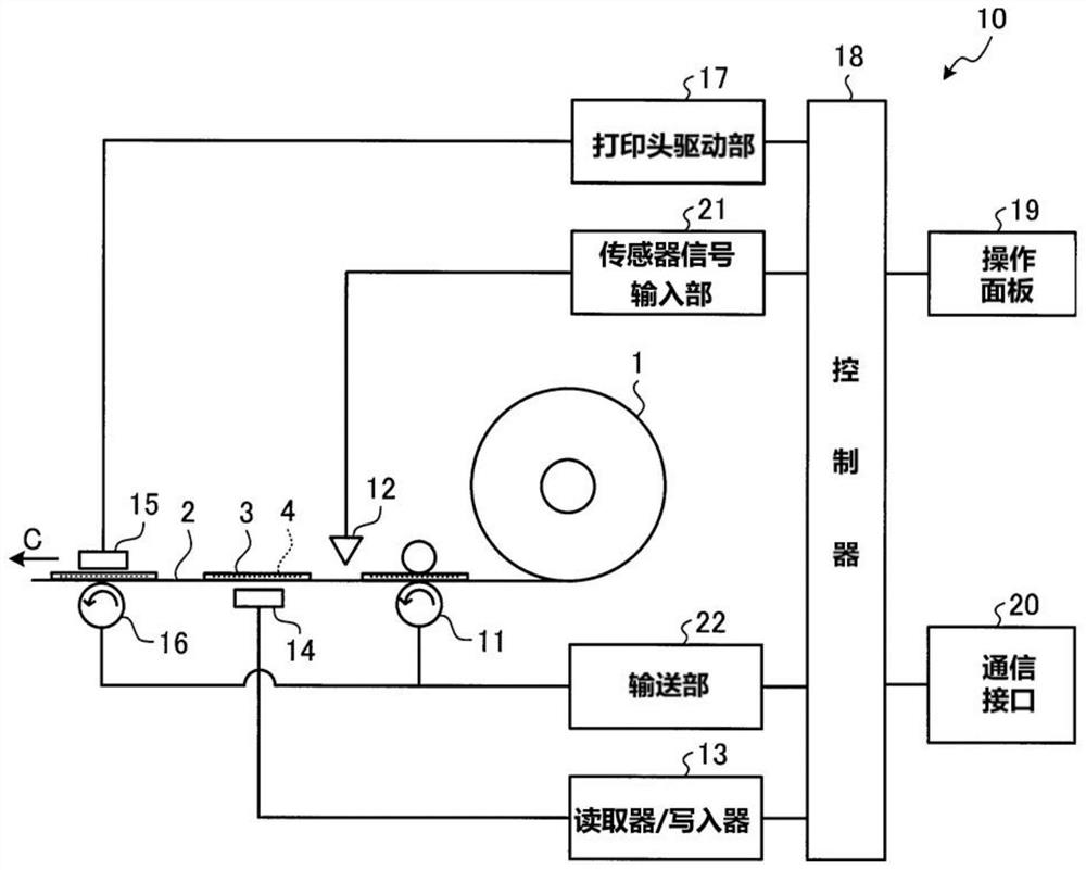
[0136] In the above-mentioned embodiment, the label printer 10 performed the derivation of the write condition, but the present invention is not limited thereto. For example, the writing condition may be derived in an information processing device such as a host device connected to the label printer 10 .

[0137] In this case, the information processing device realizes the calibration processing unit 303 (the position identification unit 3032, the measurement unit 3033, and the condition derivation unit 3034) in cooperation with the processor (CPU) of the own device and the program stored in the storage device. function. Then, the information processing device executes the calibration process described above by controlling each part of the label printer 10 , and sets the derived write conditions in the label printer 10 .

[0138] As a result, the information processing device can derive the writing conditions outside the label printer 10 , so the writing conditions can be der...


PUM


Abstract

The present invention discloses a wireless tag writing device, a calibration method, and a storage medium. The wireless tag writing device comprises: a conveyance unit for conveying a sheet on which awireless tag is provided; a transmission unit that is disposed on the conveyance path of the sheet and transmits a first radio wave for communicating with the wireless tag; a reception unit that receives a second radio wave transmitted from the wireless tag in response to the first radio wave; a measuring means for reducing a radio wave intensity of a specific level excluding a minimum level fromamong radio wave intensities of a plurality of levels transmittable by the transmitting unit to a radio wave intensity of a level at which the radio wave intensity of the second radio wave received by the reception unit is less than a threshold value every time the conveyance unit conveys a predetermined amount of the sheet and acquiring a set of the radio wave intensity of the first radio wave and the radio wave intensity of the second radio wave; and a deriving means for deriving a writing condition for writing of the wireless tag based on the set of the radio wave intensity of the first radio wave and the radio wave intensity of the second radio wave acquired for each conveying position of the sheet.

Description

[0001] This application claims the priority of the Japanese application with the application date of August 19, 2019 and the application number JP2019-150003, and cites the content of the above application, which is incorporated herein by reference in its entirety. technical field [0002] Embodiments of the present invention relate to a wireless tag writing device, a calibration method and a storage medium. Background technique [0003] In a printer device that prints on label paper to which a wireless tag such as an RFID (Radio Frequency Identification) tag is attached, the following processing is performed when determining a writing condition of the wireless tag. First, the actually used wireless tags are transported at a predetermined transport pitch. When stopping at each delivery position, radio waves are sequentially transmitted at a plurality of radio wave strengths, and the radio wave strength of the response wave received from the wireless tag is recorded in associ...

Claims


Application Information

Patent Timeline
Patent Type & Authority Applications(China)
IPC IPC(8): G06K17/00
CPCG06K17/0029
Inventor 土本宏志
Owner TOSHIBA TEC KK
Why Eureka
Try Eureka