Communication device and recording medium

A communication device and the technology of the communication department, which are applied in the direction of secure communication devices, data exchange through path configuration, transportation and packaging, etc., can solve problems such as program complexity

Active Publication Date: 2020-09-04
NAGOYA UNIVERSITY +3
View PDF10 Cites 0 Cited by
  • Summary
  • Abstract
  • Description
  • Claims
  • Application Information

AI Technical Summary

Problems solved by technology

[0002] In recent years, the ECU (Electronic Control Unit: Electronic Control Unit) mounted on a vehicle has become more functional, and the programs executed in the ECU have also become more complicated.

Method used


Image

  • Communication device and recording medium
  • Communication device and recording medium
  • Communication device and recording medium

Examples


Embodiment approach 1

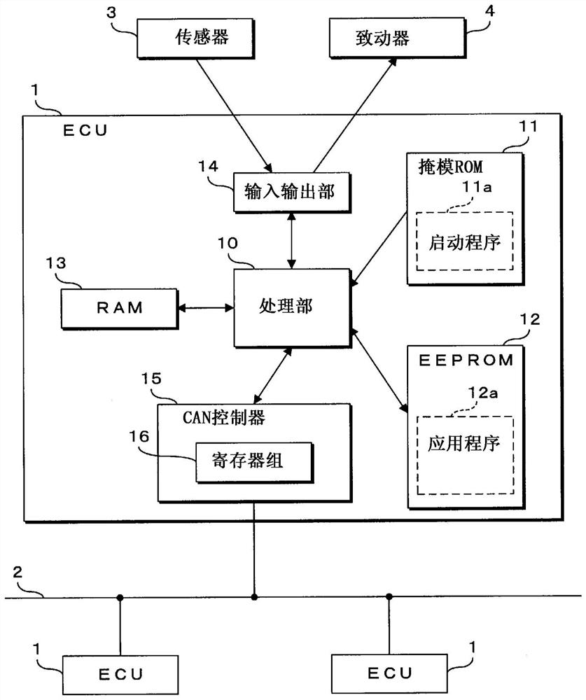
[0052] Hereinafter, the present invention will be specifically described based on drawings showing embodiments of the present invention. figure 1 It is a block diagram showing the structure of the communication system of this embodiment. The communication system of the present embodiment has a configuration in which a plurality of ECUs (communication devices) 1 mounted on a vehicle (not shown) are connected to a CAN bus 2 , and the plurality of ECUs 1 communicate via the CAN bus 2 . In addition, since a plurality of ECU1 has substantially the same structure regarding the communication function, in figure 1 The detailed configuration of one ECU 1 is shown in the figure, and the illustration of the detailed configuration of the other ECU 1 is omitted.

[0053] The ECU 1 includes a processing unit 10 , a mask ROM (first storage unit) 11 , an EEPROM (second storage unit) 12 , a RAM 13 , an input / output unit 14 , a CAN controller (communication unit) 15 , and the like. The proces...

Embodiment approach 2

[0108] Figure 8 It is a block diagram showing the structure of the communication system of Embodiment 2. In addition, in Figure 8 , omitting the figure 1 Diagram of other ECU1, sensor 3 and actuator 4 etc. shown in . The communication system according to Embodiment 2 includes setting device 205 connected to ECU 201 via communication line 206 . The setting device 205 is a device used, for example, when maintenance, inspection, etc. are performed at a vehicle dealer, a repair shop, or the like. By connecting the setting device 205 to the ECU 201 , values ​​can be written into the register group 16 of the CAN controller 15 . The setting device 205 has a display unit 251 such as a liquid crystal panel, and an operation unit 252 such as a switch or a touch panel.

[0109] ECU 201 according to Embodiment 2 does not have mask ROM 11 provided in ECU 1 according to Embodiment 1, but stores startup program 11 a in EEPROM 12 . In the EEPROM 12 of the ECU 201, a startup program 11...


PUM


Abstract

Provided are a communication device and a recording medium capable of suppressing illegal messages from being sent to a network due to injection of illegal programs. ECU (1) has: CAN controller (15), has the register bank (16) that the value relevant to the communication of other ECU (1) is stored; And processing part (10), this register bank (16) Communication processing is performed for writing and reading values. The ECU (1) switches between the full control mode and the limited mode. The full control mode is a mode in which the register set (16) of the CAN controller (15) can be written and read. The limited mode limits A mode for writing and reading a part of registers in the register group (16). The ECU ( 1 ) sets the full control mode for a predetermined period from activation, and switches from the full control mode to the limited mode after the predetermined period has elapsed. After switching to limited mode, ECU (1) will not switch to full control mode.

Description

technical field [0001] The present invention relates to a communication device for preventing illegal messages from being sent to a network, and a recording medium in which a communication restriction program is recorded. Background technique [0002] In recent years, ECUs (Electronic Control Units: Electronic Control Units) mounted on vehicles have become more functional, and along with this, the programs executed by the ECUs have also become more complicated. In addition, a plurality of ECUs are mounted on a vehicle, and these plurality of ECUs are connected via a network such as CAN (Controller Area Network: Controller Area Network). Multiple ECUs perform processing while exchanging information via a network. [0003] In Patent Document 1, the following CAN system is described: when the first node of the CAN system fails to receive the frame and becomes an error passive state, it sends a retransmission request frame, and stores the information sent by the second node to ...

Claims


Application Information

Patent Timeline
Patent Type & Authority Patents(China)
IPC IPC(8): H04L12/28B60R16/023G06F12/14H04L29/06
CPCG06F12/14H04L12/4625H04L9/40H04L12/28B60R16/023H04L2012/40215H04L2012/40273
Inventor 本田晋也高田广章仓地亮上田浩史
Owner NAGOYA UNIVERSITY
Why Eureka
Try Eureka