Wire-driven snake-shaped arm robot capable of realizing bending motion decoupling

A technology of bending motion and robotics, applied in the field of robotics, can solve problems such as increasing the difficulty of control

Active Publication Date: 2021-02-26
CHANGSHA UNIVERSITY OF SCIENCE AND TECHNOLOGY
View PDF8 Cites 4 Cited by
  • Summary
  • Abstract
  • Description
  • Claims
  • Application Information

AI Technical Summary

Problems solved by technology

[0005] In order to solve the problem that the joints of the wire-driven robot are coupled to each other during the driving process, the control difficulty is increased due to the coupling of the wires on the two degrees of freedom. The present invention provides a wire-driven snake-arm robot that realizes decoupling of bending motion

Method used


Image

  • Wire-driven snake-shaped arm robot capable of realizing bending motion decoupling
  • Wire-driven snake-shaped arm robot capable of realizing bending motion decoupling
  • Wire-driven snake-shaped arm robot capable of realizing bending motion decoupling

Examples


Embodiment 1

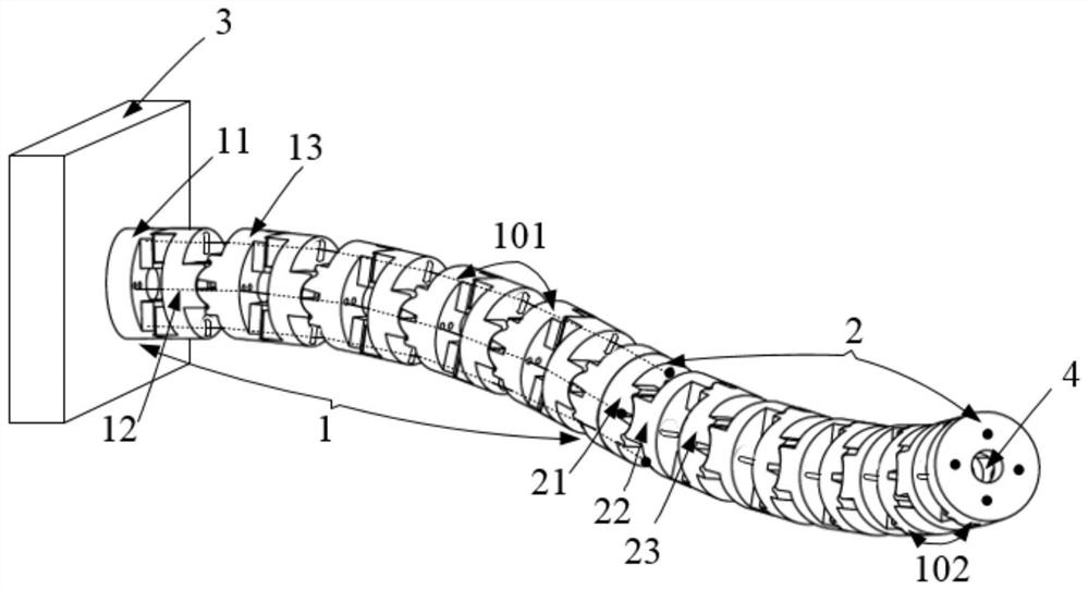
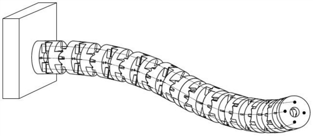
[0053] As shown in Figures 1 to 3, this embodiment discloses a wire-driven snake-arm robot that can realize decoupling of bending motion, including

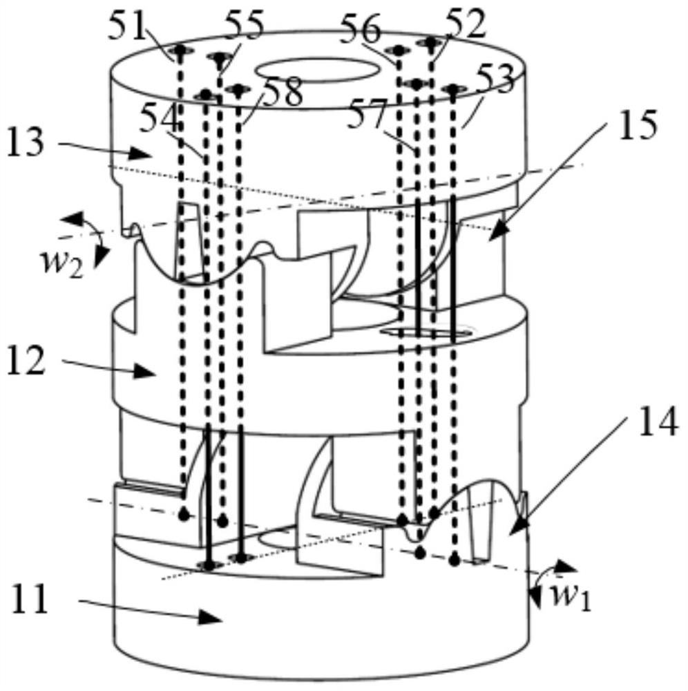
[0054] The proximal joint 1 includes a proximal joint 101; the proximal joint 101 includes a proximal base plate 11, a proximal link 12 and a proximal end plate 13, and the proximal base plate 11 is connected to the proximal joint. The rods 12 are connected to form a first rotation pair 14, the rotation axis of the first rotation pair 14 coincides with the end surface of the proximal base plate 11; the proximal end plate 13 and the proximal connecting rod 12 form a second rotation pair 15, the rotation axis of the second rotating pair 15 coincides with the end face of the proximal end disk 13;

[0055] The distal joint 2 is fixedly connected with the proximal joint 1; the distal joint 2 includes a distal joint 102, and the distal joint 102 includes a distal base plate 21, a distal connecting rod 22 and a distal The end disk 23, ...

Embodiment 2

[0084] This embodiment discloses a wire-driven serpentine arm robot capable of decoupling bending motion, which includes a proximal joint 1 and a proximal joint 101; the proximal joint 101 includes a proximal base plate 11, a proximal The connecting rod 12 and the proximal end disk 13, the proximal base disk 11 is connected with the proximal connecting rod 12 to form a first rotating pair 14, the rotation axis of the first rotating pair 14 is connected to the proximal base disk 11 The end faces are coincident; the proximal end disc 13 and the proximal connecting rod 12 form a second rotating pair 15, and the rotation axis of the second rotating pair 15 coincides with the end face of the proximal end disc 13;

[0085] The distal joint 2 is fixedly connected with the proximal joint 1; the distal joint 2 includes a distal joint 102, and the distal joint 102 includes a distal base plate 21, a distal connecting rod 22 and a distal The end disk 23, the distal base disk 21 is connect...


PUM


Abstract

The invention discloses a wire-driven snake-shaped arm robot capable of realizing bending motion decoupling. The wire-driven snake-shaped arm robot capable of realizing bending motion decoupling comprises a near-end structure section, a far-end structure section, driving wires and a driving device; wherein the near-end structure section comprises a near-end joint provided with a first revolute pair and a second revolute pair; the rotating axis of the first revolute pair coincides with the end surface of a near-end base disc; the rotating axis of the second rotating pair coincides with the endface of a near-end tail end disc; the far-end structure joint comprises a far-end joint provided with a third revolute pair and a fourth revolute pair; the rotating axis of the third revolute pair coincides with the end face of a far-end base disc; the rotating axis of the fourth revolute pair coincides with the end face of a far-end tail end disc; and extension or retraction of all the driving wires is controlled through the driving device; therefore, bending of the wire-driven snake-shaped arm robot is controlled; and bending motion decoupling is achieved in the bending process, therefore, kinematics of the robot can be effectively simplified, and the control difficulty is reduced.

Description

technical field [0001] The invention relates to the field of robots, in particular to a wire-driven serpentine-arm robot capable of decoupling bending motion. Background technique [0002] Since the wire-driven serpentine arm robot can realize multi-degree-of-freedom bending motion, it can work flexibly in a complex environment with limited height, and is widely used in maintenance inspection, minimally invasive surgery and other fields. In recent years, the types of joints that can be used to construct wire-driven snake-arm robots are rich and diverse. According to the joint degrees of freedom, they can be divided into single-degree-of-freedom or two-degree-of-freedom. The common single-degree-of-freedom joints include single-degree-of-freedom fixed-axis rotary joints, Plate and cylindrical rolling joints, etc.; two-degree-of-freedom joints include axis intersecting type (universal joint / ball joint) fixed axis rotating joint, axis non-intersecting fixed axis rotating joint,...

Claims


Application Information

Patent Timeline
Patent Type & Authority Applications(China)
IPC IPC(8): B25J9/06
CPCB25J9/065
Inventor 黄龙刘北尹来容丁浩段超
Owner CHANGSHA UNIVERSITY OF SCIENCE AND TECHNOLOGY
Why Eureka
Try Eureka