
Radar, photoelectricity and interference integrated detection-suppression device and method

A photoelectric detection and radar technology, applied in measuring devices, radio wave measurement systems, radio wave reflection/re-radiation, etc., can solve the complex software design and data processing of radar azimuth, affect the normal transmission and reception of radar signals, and software algorithms Complexity and other issues, to achieve the effect of simplifying motion control, simplifying complexity, and reducing overall volume

Pending Publication Date: 2021-02-26
上海神添实业有限公司 +1
View PDF4 Cites 1 Cited by
  • Summary
  • Abstract
  • Description
  • Claims
  • Application Information

AI Technical Summary

Problems solved by technology

However, due to the characteristics of the turntable rotation, the radar also revolves along with the rotation of the turntable while its own rotation, so the radar azimuth is relatively complicated in software design and data processing
At the same time, since the radar and photoelectric monitoring equipment are integrated on a turntable, the volume of the turntable is relatively increased.
That is to say, the structure of the same turntable with different axes is characterized by high system reliability and relatively good maneuverability, but the software algorithm is relatively complicated and the turntable is too large
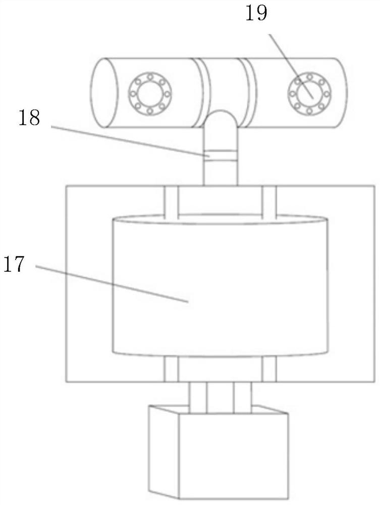
[0006] Additionally, if figure 1 As shown, in some radar photoelectric monitoring equipment, there needs to be a support rod 18 as a support between the machine-scanned radar 17 and the camera 19, and the support rod 18 will affect the normal transmission and reception of radar signals during use.

Method used


Image

  • Radar, photoelectricity and interference integrated detection-suppression device and method
  • Radar, photoelectricity and interference integrated detection-suppression device and method
  • Radar, photoelectricity and interference integrated detection-suppression device and method

Examples


Embodiment Construction

[0036] The following will clearly and completely describe the technical solutions in the embodiments of the present invention with reference to the accompanying drawings in the embodiments of the present invention. Obviously, the described embodiments are only some, not all, embodiments of the present invention. Based on the embodiments of the present invention, all other embodiments obtained by persons of ordinary skill in the art without making creative efforts belong to the protection scope of the present invention.

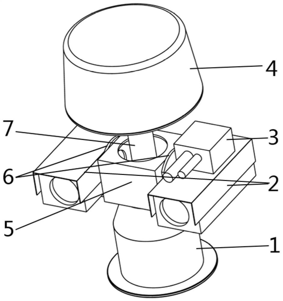
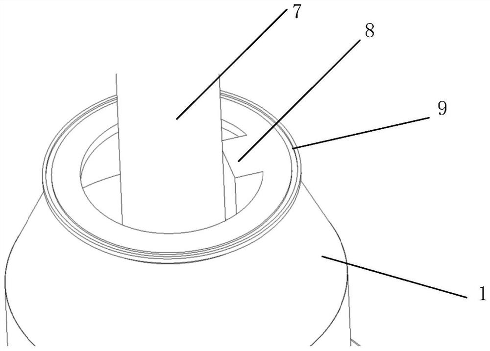
[0037] Such as figure 2 As shown, the present invention provides a radar 4, an integrated photoelectric and interference detection-suppression device, including: a controller (not shown in the figure), a servo hollow rotating platform 1, an azimuth mechanism 5, at least one photoelectric detection device 2, At least one pitching mechanism 6 , interference suppression equipment 3 , support column 7 , and radar 4 .

[0038] Such as image 3 , Figure 4 As sh...


PUM


Abstract

The invention provides a radar, photoelectricity and interference integrated detection-suppression device. The device comprises a controller, a servo hollow rotating platform, an orientation mechanism, at least one pitching mechanism, a radar, at least one photoelectric detection device, an interference suppression device and a supporting stand column. The photoelectric detection device, the interference suppression device and the orientation mechanism are driven by the servo hollow rotating platform to synchronously move in the azimuth direction in an integrated manner; the photoelectric detection device and the interference suppression device also move in the pitching direction through a pitching mechanism; the bottom of the supporting stand column penetrates through the orientation mechanism and is fixedly connected with the servo hollow rotating platform. The radar is rotationally connected with the top end of the supporting stand column through a radar servo mechanism at the bottom, and the radar and the orientation mechanism move independently in the azimuth direction. The invention further provides a target detection-suppression method.

Description

technical field [0001] The invention relates to the technical field of low-altitude aircraft detection, in particular to a radar, photoelectric and interference integrated detection-suppression device and method for detecting and suppressing low-altitude aircraft. Background technique [0002] In the existing technology in the field of civil aviation air traffic control, radar is usually used to search for targets for low-altitude aircraft, and then the target information is sent to photoelectric monitoring equipment for further tracking, monitoring and evidence collection, and then the target is disposed of through jamming equipment. Through the way of multi-device cooperative work, to a certain extent, the problem of untimely disposal caused by the instantaneous shadowing of the target when a single detection source detects small low-altitude targets is solved, and information complementation is realized. [0003] With regard to the cooperative operation of radar, photoele...

Claims


Application Information

Patent Timeline
Patent Type & Authority Applications(China)
IPC IPC(8): G01S13/86G01S7/38
CPCG01S13/86G01S7/38
Inventor 聂潇乾严鹏王炳琪吴彬彬高承帅陈光绪
Owner 上海神添实业有限公司
Learn More