Radio frequency circuit, radio frequency circuit configuration method and device
A radio frequency circuit and radio frequency chip technology, which is applied in the field of communication, can solve the problems of large insertion loss of combiners and affect the reception of high frequency signals, and achieve the effect of reducing insertion loss
- Summary
- Abstract
- Description
- Claims
- Application Information
AI Technical Summary
Problems solved by technology
Method used
Image
Examples
Embodiment 1
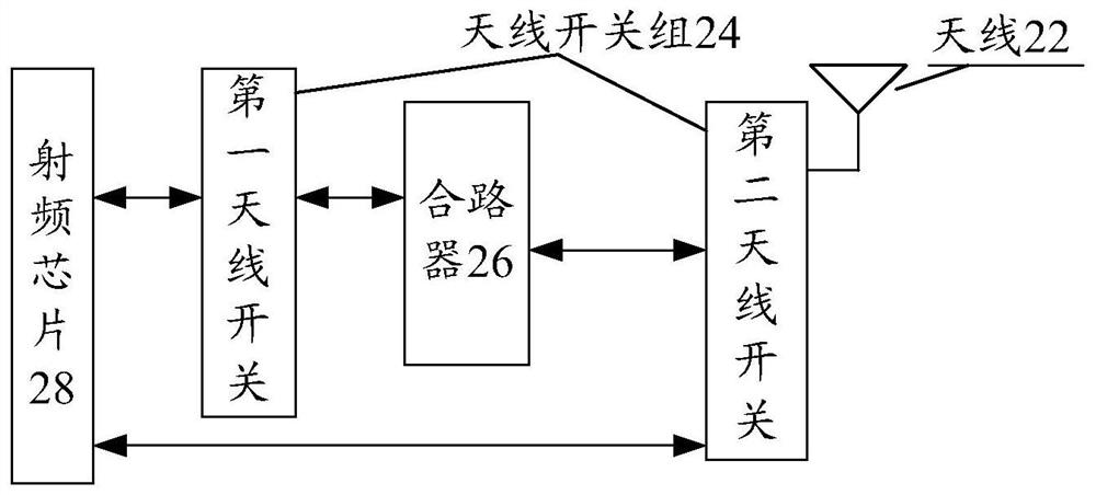
[0044] Radio frequency circuit is provided for operating a mobile terminal in the present embodiment, figure 2 It is a schematic structural diagram of a radio frequency circuit of the embodiment of the present invention, such as figure 2 As shown, the radio frequency circuit comprises:
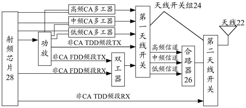
[0045] Antenna 22, antenna switch group 24, multiplexer 26 and the RF chip 28; wherein an output port of the RF chip 28 are respectively input of the first group of antenna switch 24 connected to the antenna switch, and a second switch group 24 and the antenna an input terminal connected to the second antenna switch; a first antenna switch, a signal for classifying non-polymeric carrier, to obtain various types of signal frequencies; input of multiplexer 26 to the output terminal of the first switch is connected to the antenna, combiner an output terminal 26 and the second antenna switch is connected, a signal for performing combination of various types of frequency; second antenna switch input te...
Embodiment 2
[0076] Configuration provides a method for operating the RF circuit to the RF circuit in the present embodiment, Image 6 Is a flowchart of a method for configuring a radio frequency circuit of the present embodiment of the invention, as Image 6 As shown, the process includes the following steps:
[0077] Step S602, in case of receiving a radio frequency signal through an antenna, a radio frequency signal includes determining a predetermined frequency band signal;
[0078] Step S604, the determination result is YES in the case where isolated by a radio frequency signal from the second antenna switch in a predetermined frequency band signal;
[0079] Step S606, the preset frequency band signal is returned to the RF chip, wherein the second antenna switch returns other signals to a predetermined frequency band signal separated by the first RF chip antenna switch.
[0080] RF circuit configuration method according to an embodiment of the present application, since in case of receiving...
Embodiment 3
[0093] In the present embodiment, the configuration is also provided an apparatus for the RF circuit, the means for achieving the above examples and preferred embodiment has been described will not be repeated. As used herein, the term "module" can achieve a combination of software and / or hardware of a predetermined function. Although the apparatus described in the following examples is preferably implemented in software, the implementation of hardware, or combinations of software and hardware may also be conceived.
[0094] Figure 7 It is a block diagram configuration of the radio apparatus circuit of the embodiment of the present invention, such as Figure 7 , The apparatus comprising: a determining module 72, a signal separation module 74 and a signal receiving module 76, wherein,
[0095] Determining module 72, configured to, when receiving RF signals through an antenna, a radio frequency signal includes determining a predetermined frequency band signal; signal separation mo...
PUM
 Abstract
Description
Claims
Application Information
 - R&D
- Intellectual Property
- Life Sciences
- Materials
- Tech Scout
- Unparalleled Data Quality
- Higher Quality Content
- 60% Fewer Hallucinations
Browse by: Latest US Patents, China's latest patents, Technical Efficacy Thesaurus, Application Domain, Technology Topic, Popular Technical Reports.
© 2025 PatSnap. All rights reserved.Legal|Privacy policy|Modern Slavery Act Transparency Statement|Sitemap|About US| Contact US: help@patsnap.com


