Packaging structure applied to infrared sensor, and infrared sensor packaging method
An infrared sensor and packaging structure technology, applied in the field of sensors, can solve the problems of high assembly process requirements, high cost, and complex structure, and achieve the effects of simplifying the packaging structure and packaging production process, simple structure, and realizing fixation and protection
- Summary
- Abstract
- Description
- Claims
- Application Information
AI Technical Summary
Problems solved by technology
Method used
Image

Examples
Embodiment 1
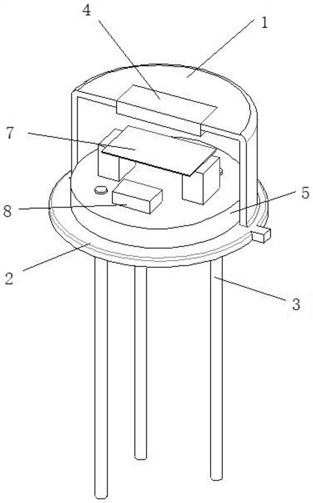
[0035] This embodiment can be applied to pyroelectric sensors, such as figure 2 The shown packaging structure applied to infrared sensors includes a substrate 5, a sensitive element 7 disposed on the substrate, a supporting circuit 8 for the sensitive element, a metal cap 1 and pins 3; the side of the substrate is closely attached to the inner wall of the metal cap close; the metal pipe cap has a rectangular receiving window 13 of 4mm x 3mm facing the receiving direction, and an infrared filter 4 matching the size of the receiving window is fixedly installed at the receiving window.
[0036] A metal wire is laid on the substrate, and the sensitive element and the supporting circuit of the sensitive element are electrically connected to the substrate through the metal wire and conductive glue to form a sensing circuit; one end of the pin is fixedly installed on the substrate, and is connected through the The conductive glue 12 is electrically connected to the pad on the substr...
Embodiment 2
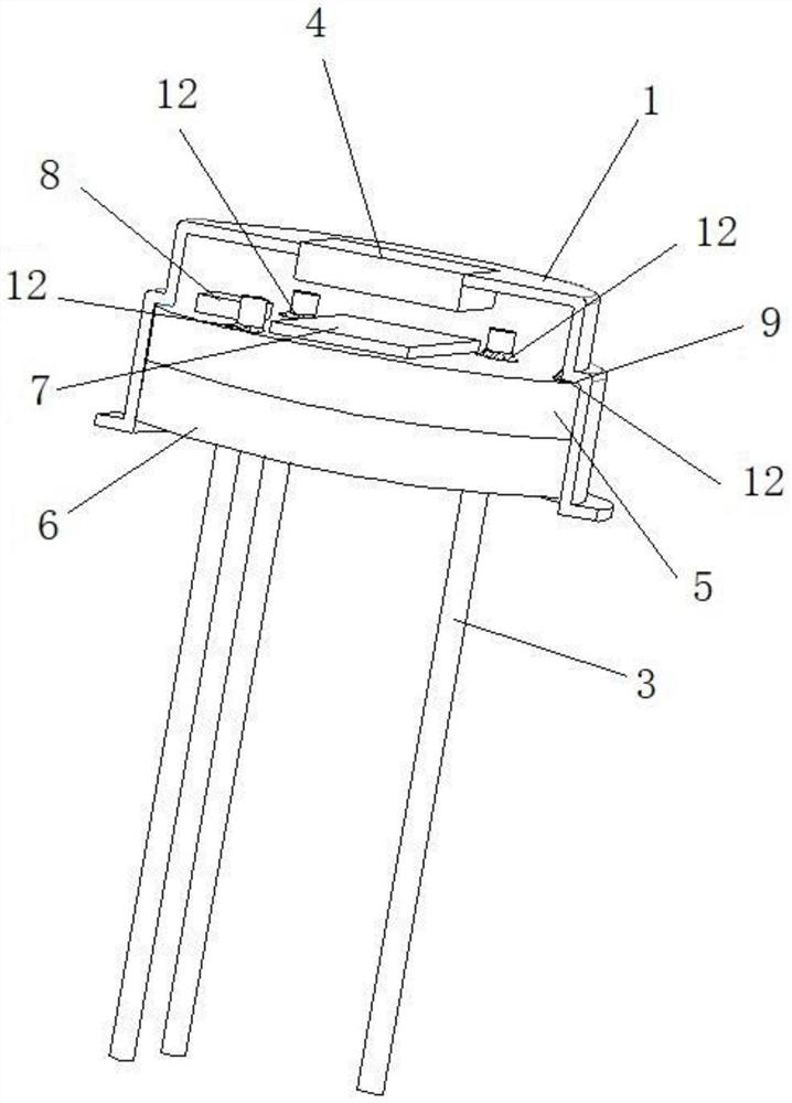
[0044] The difference from Example 1 is that, as image 3 As shown, in this embodiment, the metal pipe cap has a circular receiving window facing the receiving direction, and an infrared filter matching the size of the receiving window is fixedly installed at the receiving window.
[0045] In addition, one end of the pin is riveted on the substrate, and the other end of the pin is used as the pin of the product of this embodiment, image 3 The pins shown in are also 3.
[0046] Further, three or more clamping points 10 are provided on the metal tube cap for guiding and positioning the loading of the substrate, and when the clamping points are in contact with the solder pads on the substrate, the metal tube cap can electrical connection, so as to realize the grounding connection of the metal tube cap, and at the same time, it can also ensure that the distance between the sensitive element installed on the substrate and the infrared filter meets the design requirements, and pla...
Embodiment 3
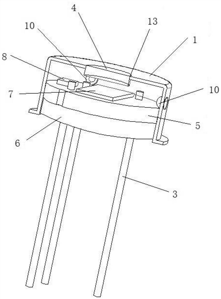
[0050] The difference from Example 1 and Example 2 is that, as Figure 4 As shown, in this embodiment, two positioning columns 11 are provided on the inner wall of the metal pipe cap, and the positioning columns are used as both an installation positioning structure and a grounding connection structure. Conduction and heat conduction, one end of the two positioning posts are installed on the substrate, and connected with the substrate through conductive glue; the other ends of the two positioning posts are supported on the inner bottom surface of the metal tube cap, and connected to the bottom surface of the metal tube cap The electrical connection is realized through conductive glue connection or direct contact; the positioning post can also be directly connected to the ground wire on the substrate to realize electrical connection, and is used to realize the grounding of the metal pipe cap. By adjusting the height of the positioning column, the distance between the sensitive ...
PUM
 Abstract
Description
Claims
Application Information
 - R&D
- Intellectual Property
- Life Sciences
- Materials
- Tech Scout
- Unparalleled Data Quality
- Higher Quality Content
- 60% Fewer Hallucinations
Browse by: Latest US Patents, China's latest patents, Technical Efficacy Thesaurus, Application Domain, Technology Topic, Popular Technical Reports.
© 2025 PatSnap. All rights reserved.Legal|Privacy policy|Modern Slavery Act Transparency Statement|Sitemap|About US| Contact US: help@patsnap.com