An Internet sensor connector

A technology of sensors and connectors, which is applied in the field of Internet sensor connectors, can solve problems such as damage to sensor connectors, communication interruptions, and adverse effects of connected equipment, and achieve the effect of ensuring stability

Active Publication Date: 2021-12-14
SHENZHEN POLYTECHNIC
View PDF3 Cites 0 Cited by
  • Summary
  • Abstract
  • Description
  • Claims
  • Application Information

AI Technical Summary

Problems solved by technology

[0003] Existing Internet sensor connectors are vulnerable to external force collisions or external force pulls applied by users unintentionally during signal communication, causing the sensor connectors to separate from the communication equipment, resulting in interruption of communication. Sudden interruption can easily cause the current to fail to correspond to the connected equipment. , if it is often done, it will cause damage to the sensor connector, and even cause certain adverse effects on the connected equipment

Method used


Image

  • An Internet sensor connector
  • An Internet sensor connector
  • An Internet sensor connector

Examples


Embodiment 1

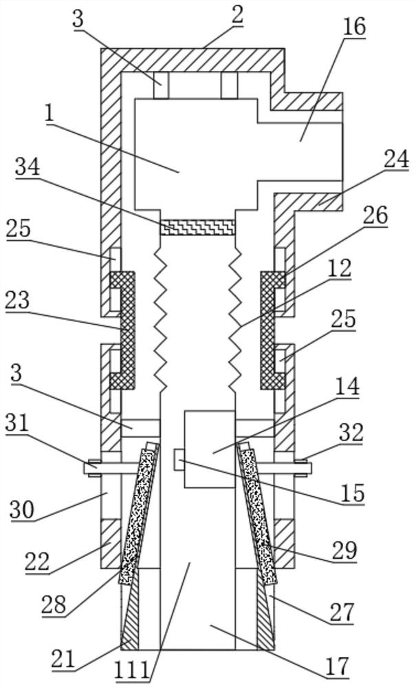
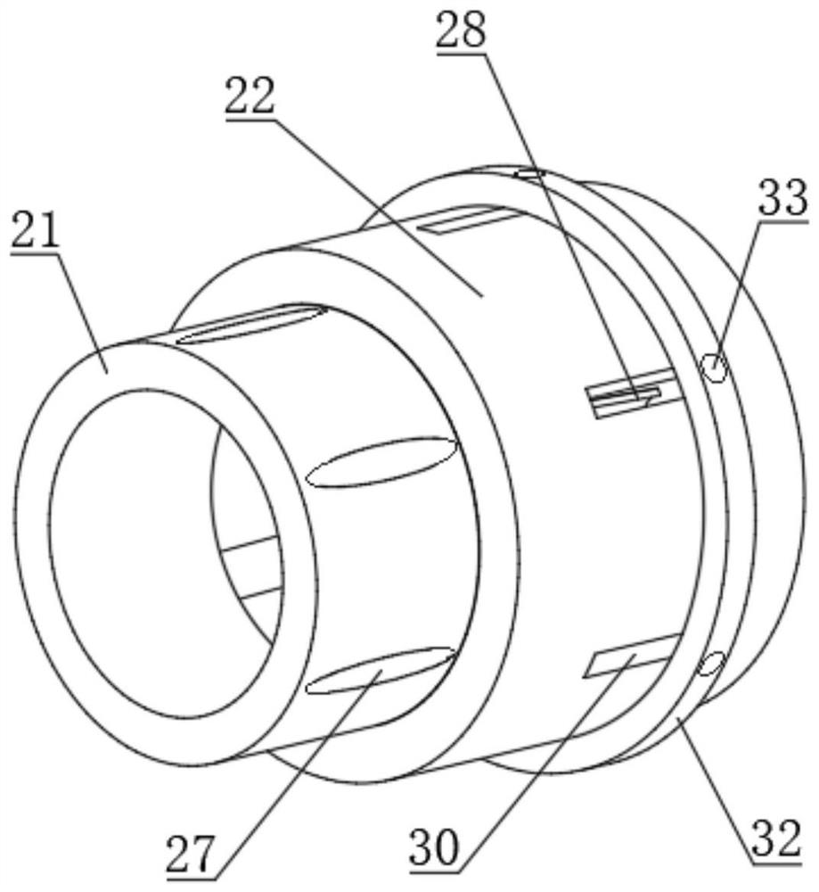
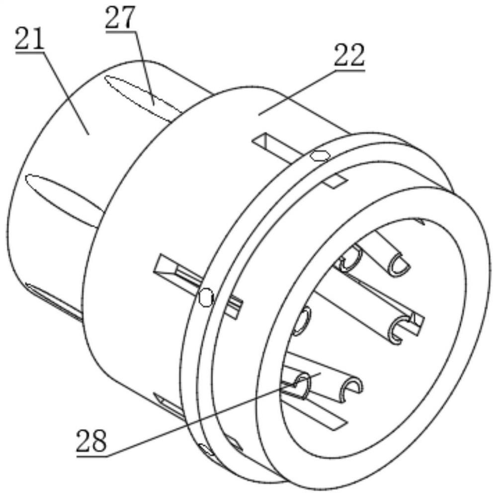
[0028] see Figure 1 to Figure 5 , an Internet sensor connection head, including a joint body 1 and an insulating shell 2, the inside of the joint body 1 is provided with a current converter 14, and the upper end and the lower end of the joint body 1 are respectively provided with a first interface 16 and a second interface 17 , the insulating shell 2 is sleeved on the outside of the joint body 1, the insulating shell 2 is composed of a fastening shell 21, a lower shell 22, a transition shell 23 and an upper shell 24, and the fastening shell 21 is set on the second On the outside of the second interface 17, the upper end surface of the fastening casing 21 is fixedly connected with the lower end surface of the lower casing 22. Several oblique through holes 27 are arranged on the outer surface of the fastening casing 21, and the oblique through holes 27 One end of one end is fixedly connected with an oblique arc guide plate 28, and the oblique arc guide plate 28 is located insid...

Embodiment 2

[0035] see Figure 1 to Figure 5 , this embodiment is a further description of the Internet sensor connector described in Example 1. In this embodiment, the inner surface at the upper end of the lower casing 22 and the inner surface at the lower end of the upper casing 24 are both An annular limiting groove 25 is provided, and an annular limiting block 26 is provided at the upper end and the lower end of the transition casing 23, and the outer surface of the annular limiting block 26 is slidably matched with the inner side wall of the annular limiting groove 25 connection, the inner diameter value of the lower casing 22 is the same as the inner diameter value of the upper casing 24, and the inner diameter value of the upper casing 24 is the same as the outer diameter value of the transition casing 23, so that the lower casing 22 and the upper casing The distance between 24 can be changed.

[0036] The joint main body 1 is composed of a lower main body 111, a middle main body ...


PUM


Abstract

The invention discloses an Internet sensor connection head, which comprises a joint body and an insulating shell. The upper end and the lower end of the joint body are respectively provided with a first interface and a second interface. The insulating shell is sleeved on the outside of the joint body. The insulating shell consists of The fastening casing is composed of a lower casing, a transition casing and an upper casing. The fastening casing is set on the outside of the second interface. Several oblique through holes are arranged on the outer surface of the fastening casing. An oblique arc guide plate is fixedly connected to one end of the through hole, and the oblique arc guide plate is located inside the lower casing, and a moving column is fixedly connected to the side of the upper end of the rubber rod. In the present invention, through the setting of oblique through holes, oblique arc guide plates, rubber rods and moving columns, after the second interface is connected with the connecting device, the moving collar is pushed to make the rubber rod slide along the oblique arc guide plates to the oblique passage. In the hole, the rubber rod is in close contact with the inner side wall of the equipment interface, so that the present invention is not easily separated from the equipment interface.

Description

technical field [0001] The invention relates to the technical field of sensor connectors, in particular to an Internet sensor connector. Background technique [0002] The Internet sensor connector is an industrial connector capable of signal connection and signal output. It has certain functions of waterproof, cold resistance, high temperature resistance and anti-interference; the Internet sensor connector is suitable for: electronic instruments, testing instruments, automobiles , electrical and electrical systems, construction machinery, industrial automation and other technical fields, the sensor connector has the characteristics of easy installation and good contact, and can be used in a relatively harsh environment. The sensor connector is currently a national standard electrical component . [0003] Existing Internet sensor connectors are vulnerable to external force collisions or external force pulls applied by users unintentionally during signal communication, causin...

Claims


Application Information

Patent Timeline
Patent Type & Authority Patents(China)
IPC IPC(8): H01R13/639
CPCH01R13/639
Inventor 范新灿
Owner SHENZHEN POLYTECHNIC
Why Eureka
Try Eureka