Magnetic material straightening equipment
A magnetic material and equipment technology, applied in the field of magnetic material alignment equipment, can solve problems such as dumping, decreased magnetic material alignment effect, and small contact area
- Summary
- Abstract
- Description
- Claims
- Application Information
AI Technical Summary
Problems solved by technology
Method used
Image


Examples
Embodiment 1
[0026] For example figure 1 -example Figure 5 Shown:
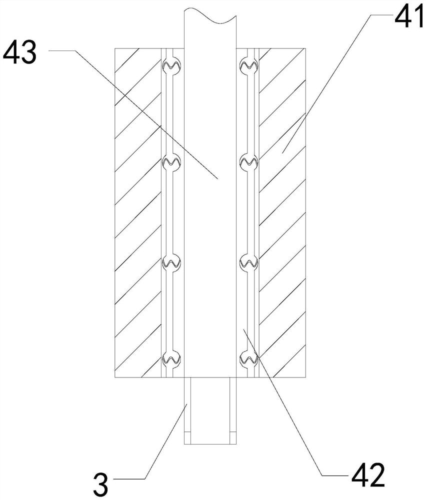
[0027] The invention provides a magnetic material straightening device, the structure of which includes a body 1, a base 2, a hopper 3, and a straightening mechanism 4. The body 1 is installed at the rear end of the base 2, and the hopper 3 is connected to the The front end of the mechanism 4 is welded, and the straightening mechanism 4 is embedded in the upper position of the base 2; the straightening mechanism 4 includes an operation table 41, a splint 42, and a transmission table 43, and the splint 42 is embedded in the operation table 41 The upper surface position, the transfer platform 43 is connected with the middle part of the operating platform 41 .
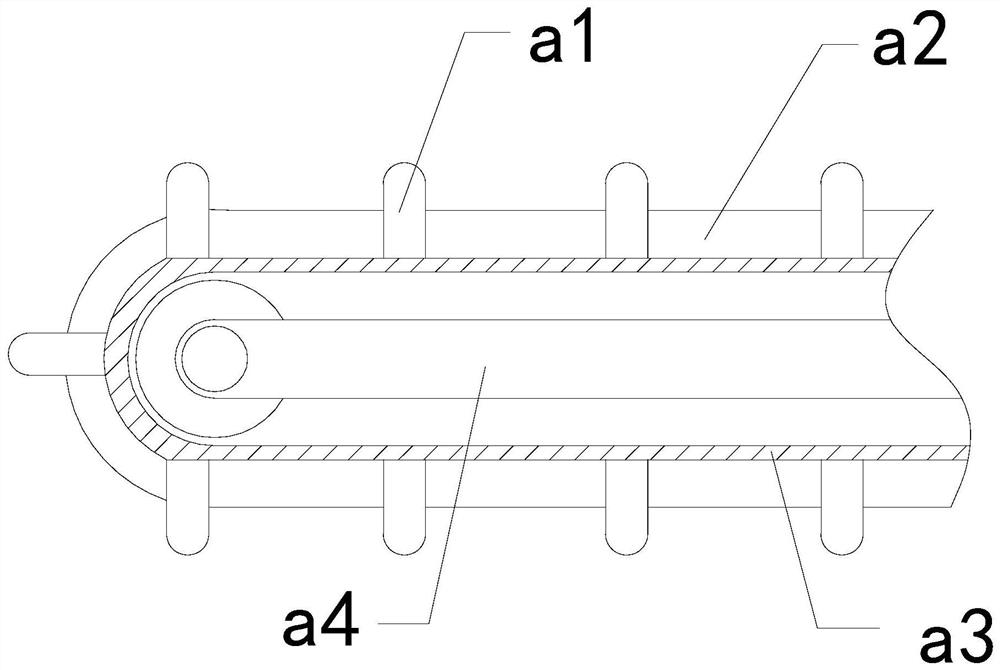
[0028] Wherein, the transfer platform 43 includes a partition a1, a contact plate a2, a transition layer a3, and a transfer frame a4, the partition a1 is embedded in the inner position of the contact plate a2, and the contact plate a2 and the transition layer a3 ar...
Embodiment 2
[0034] For example Figure 6 -example Figure 8 Shown:
[0035] Wherein, the swing plate b3 includes a receiving plate b31, a linkage rod b32, and a suction plate b33. The linkage rod b32 is movably engaged with the receiving plate b31, and the suction plate b33 is embedded and fixed on the left side of the linkage rod b32. There are three suction discs b33, which are evenly distributed in parallel on the left side of the receiving plate b31. When the suction disc b33 loses the extrusion of the object, it can slide out to the left under the cooperation of the linkage rod b32 through its own gravity.
[0036] Wherein, the adsorption disc b33 includes a disc body c1, a connecting ring c2, a vent c3, and a separation groove c4, the disc body c1 is hingedly connected with the connecting ring c2, and the vent c3 runs through the inner position of the disc body c1, The separation groove c4 and the disk body c1 are of an integrated structure, and the separation groove c4 has a tria...
PUM
 Abstract
Description
Claims
Application Information
 - R&D
- Intellectual Property
- Life Sciences
- Materials
- Tech Scout
- Unparalleled Data Quality
- Higher Quality Content
- 60% Fewer Hallucinations
Browse by: Latest US Patents, China's latest patents, Technical Efficacy Thesaurus, Application Domain, Technology Topic, Popular Technical Reports.
© 2025 PatSnap. All rights reserved.Legal|Privacy policy|Modern Slavery Act Transparency Statement|Sitemap|About US| Contact US: help@patsnap.com