Wormwood juice graded extraction device
A graded extraction and juice technology, applied in the direction of fat production, cutting equipment, presses, etc., can solve the problems of poor pressing effect, cumbersome operation, and low efficiency of manual pressing, and achieve the effect of enhancing the cutting effect
- Summary
- Abstract
- Description
- Claims
- Application Information
AI Technical Summary
Problems solved by technology
Method used
Image
Examples
Embodiment 1
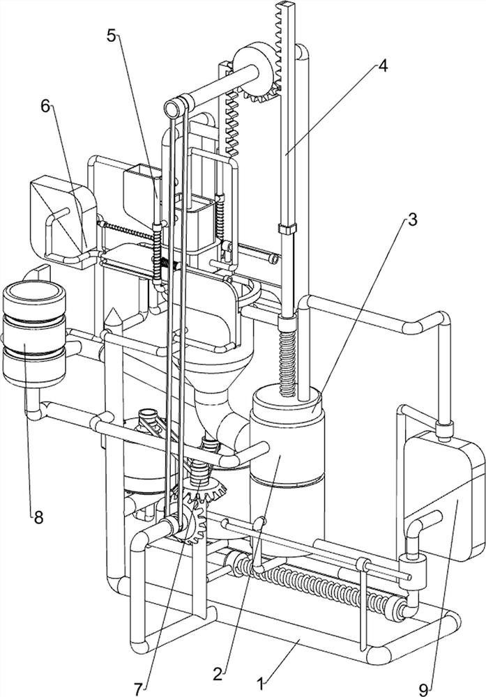
[0029] A kind of wormwood juice graded extraction device, such as figure 1 and figure 2 As shown, it includes a support frame 1, an in and out stressed net frame 2, an extruding rod 3, an automatic extruding mechanism 4, a cutting mechanism 5 and a pushing mechanism 6, the supporting frame 1 is provided with an in and out stressed net frame 2, and the in and out Sliding extrusion rods 3 are provided in the stress net frame 2, and an automatic extrusion mechanism 4 is provided on the support frame 1. The automatic extrusion mechanism 4 is connected with the in and out stress net frame 2 and the extrusion rod 3. The upper left side of frame 2 is provided with cutting mechanism 5, and cutting mechanism 5 engages with automatic extruding mechanism 4, and the upper part of entering and leaving the stressed net frame 2 is provided with pushing mechanism 6, and pushing mechanism 6 is connected with cutting mechanism 5.
[0030] When people need to extract wormwood juice from wormwo...
Embodiment 2
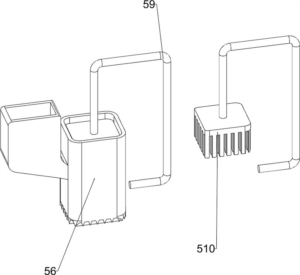
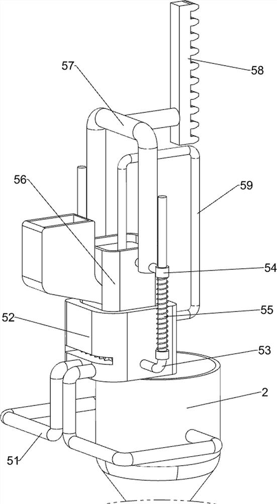
[0032] On the basis of Example 1, such as image 3 , Figure 4 , Figure 5 and Image 6 As shown, the automatic extrusion mechanism 4 includes a first fixed rod 41, a motor 42, a first rotating shaft 43, a bevel gear 44, a first transmission assembly 45, a second fixed rod 46, a second transmission assembly 47, a half gear 48, The first rack 49, the first sliding sleeve 410, the first spring 411 and the second rotating shaft 412; The upper front rotating type is provided with a first rotating shaft 43, and the first rotating shaft 43 top and the first fixed rod 41 top are all provided with a bevel gear 44, and the two bevel gears 44 mesh, and the bevel gear 44 on the first fixed rod 41 top is connected to the first fixed rod 41 top. A fixed rod 41 is rotationally connected, a first transmission assembly 45 is connected between the first rotating shaft 43 top and the output shaft of the motor 42, and a second fixed rod 46 is provided on the rear side of the upper part of the...
Embodiment 3
[0039] On the basis of Example 2, such as Figure 7 , Figure 8 and Figure 9 Shown, also comprise rotary cutting mechanism 7, be provided with rotary cutting mechanism 7 on the screen frame 2 that enters and exits force, rotary cutting mechanism 7 is connected with first rotating shaft 43, and rotary cutting mechanism 7 includes rotating bar 71, The 3rd transmission assembly 72 and rotary knife 73, in and out of force net frame 2, rotary type is provided with rotating bar 71, is connected with the 3rd transmission assembly 72 between rotating bar 71 bottoms and first rotating shaft 43, and rotating bar 71 tops are evenly arranged. Rotary knife 73 is arranged.
[0040] The first rotating shaft 43 rotates and drives the third transmission assembly 72 to drive, thereby driving the rotating rod 71 to rotate, and then driving the rotating knife 73 to rotate, so that the rotating knife 73 can perform rotary cutting on the wormwood that has been cut in and out of the stressed net ...
PUM
 Abstract
Description
Claims
Application Information
 - R&D
- Intellectual Property
- Life Sciences
- Materials
- Tech Scout
- Unparalleled Data Quality
- Higher Quality Content
- 60% Fewer Hallucinations
Browse by: Latest US Patents, China's latest patents, Technical Efficacy Thesaurus, Application Domain, Technology Topic, Popular Technical Reports.
© 2025 PatSnap. All rights reserved.Legal|Privacy policy|Modern Slavery Act Transparency Statement|Sitemap|About US| Contact US: help@patsnap.com


