Pomegranate juicing equipment for wine brewing
A technology for squeezing juice and equipment, which is applied in the field of pomegranate juice squeezing equipment for wine making, and can solve the problems of low juice yield and easy influence on the progress of juice squeezing
- Summary
- Abstract
- Description
- Claims
- Application Information
AI Technical Summary
Problems solved by technology
Method used
Image
Examples
Embodiment 1
[0066] A pomegranate juicer for wine making, such as figure 1 As shown, it includes a base 1, a slagging mechanism 2, a slag scraping mechanism 3 and a juice extracting mechanism 4. The slagging mechanism 2 is arranged in the middle of the base 1, and the slag scraping mechanism 3 is arranged on the right side of the slagging mechanism 2. A juicing mechanism 4 is arranged between the front and rear sides in the middle of the seat 1, and a collection frame is placed on the base 1.
[0067]When people need to squeeze pomegranates for wine making, they can use this kind of pomegranate equipment for wine making. When the juicing mechanism 4 moves downward, the juicing mechanism 4 can squeeze the pomegranate juice, and the squeezed pomegranate juice will flow to the collection frame. At this time, the juice extracting mechanism 4 is closed, and people then pull the slag-discharging mechanism 2 to move to the right. Due to the gravity of the accumulated pomegranate residue and the ...
Embodiment 2
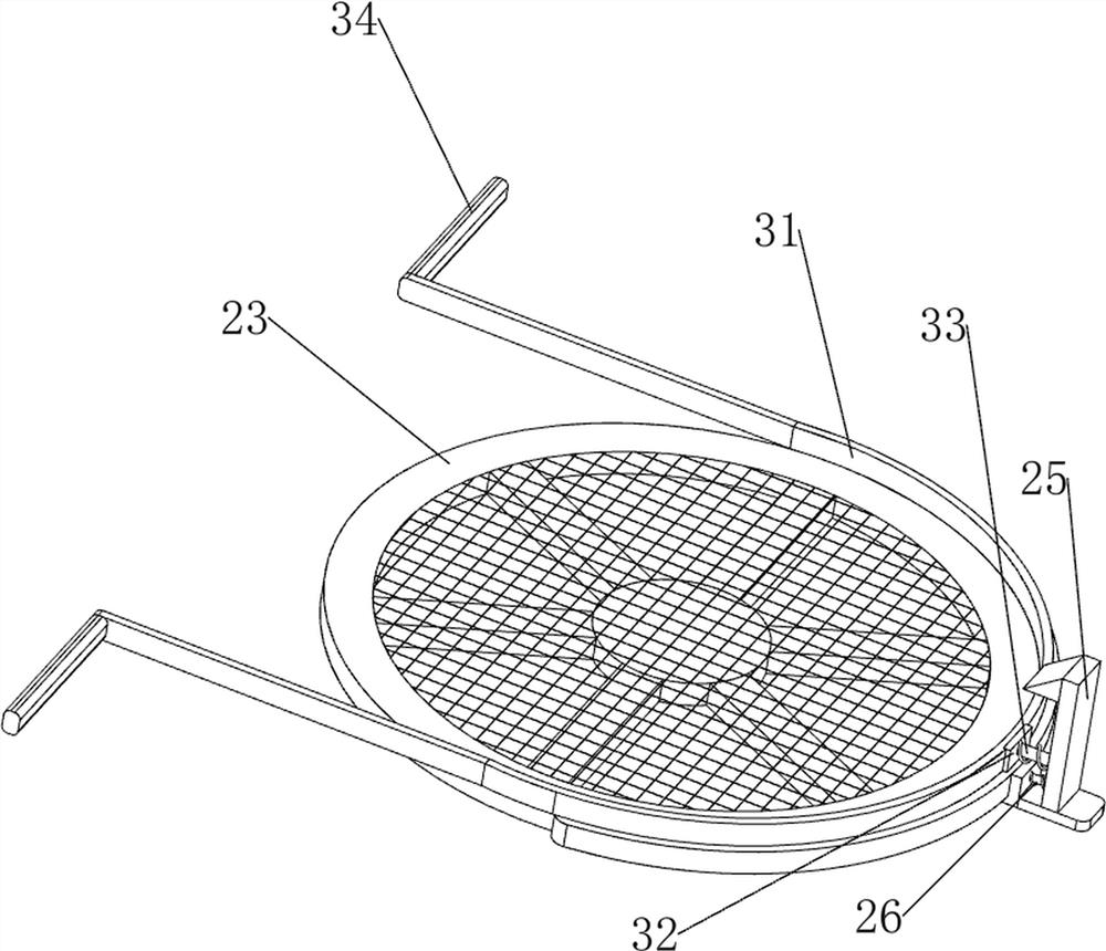
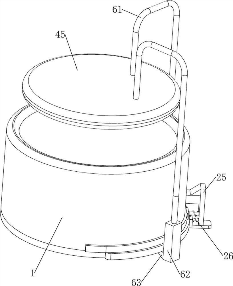
[0069] On the basis of Example 1, such as Figure 2-Figure 4 As shown, the slag discharge mechanism 2 includes a first fixed block 21, a first telescopic assembly 22, an extruded sieve plate 23, a second fixed block 24, a clamping block 25 and a second telescopic assembly 26. The upper part of the side is provided with a first fixed block 21, the lower part of the middle right side on the base 1 is provided with a second fixed block 24, the bottom of the first fixed block 21 on both sides is provided with a first telescopic assembly 22, and the first telescopic assembly 22 is provided on both sides. An extruded sieve plate 23 is arranged between the bottoms of the telescopic components 22, and a block 25 is slidingly provided on the top right side of the extruded sieve plate 23, and the block 25 cooperates with the second fixed block 24, and the block 25 and the extruded sieve plate 23 A second telescopic assembly 26 is connected therebetween.
[0070] After the pomegranate j...
Embodiment 3
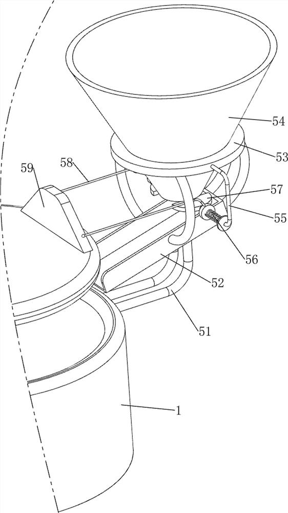
[0076] On the basis of Example 2, such as Figure 5-Figure 7 As shown, a material control mechanism 5 is also included, and the material control mechanism 5 includes a second support frame 51, a material guide plate 52, a third support frame 53, a material box 54, a first connecting rod 55, a fifth telescopic assembly 56, The baffle plate 57, the first special-shaped rod 58 and the first wedge-shaped block 59, the upper and outer walls of the front and rear parts in the middle of the base 1 are provided with a second support frame 51, and the tops of the second support frames 51 on both sides are symmetrically provided with guide materials. Plate 52, the outer side of material guide plate 52 is provided with the 3rd supporting frame 53, and the inner wall of the upper side of the 3rd supporting frame 53 is provided with material box 54, and the left and right sides of the 3rd supporting frame 53 tops are all provided with the first connecting rod 55, the first connecting rod 55...
PUM
 Abstract
Description
Claims
Application Information
 - R&D
- Intellectual Property
- Life Sciences
- Materials
- Tech Scout
- Unparalleled Data Quality
- Higher Quality Content
- 60% Fewer Hallucinations
Browse by: Latest US Patents, China's latest patents, Technical Efficacy Thesaurus, Application Domain, Technology Topic, Popular Technical Reports.
© 2025 PatSnap. All rights reserved.Legal|Privacy policy|Modern Slavery Act Transparency Statement|Sitemap|About US| Contact US: help@patsnap.com


