A cable core recovery separator

A separator and cable core technology, applied in the field of cable core recovery separators, can solve the problems of cumbersome and slow cables

Active Publication Date: 2022-08-05
国网湖北省电力有限公司黄石供电公司 +1
View PDF4 Cites 0 Cited by
  • Summary
  • Abstract
  • Description
  • Claims
  • Application Information

AI Technical Summary

Problems solved by technology

[0005] In order to overcome the cumbersome and slow shortcomings of manual cable separation by workers, the technical problem of the present invention is to provide a cable core recovery separator that can automatically cut and separate cables automatically

Method used


Image

  • A cable core recovery separator
  • A cable core recovery separator
  • A cable core recovery separator

Examples


Embodiment 1

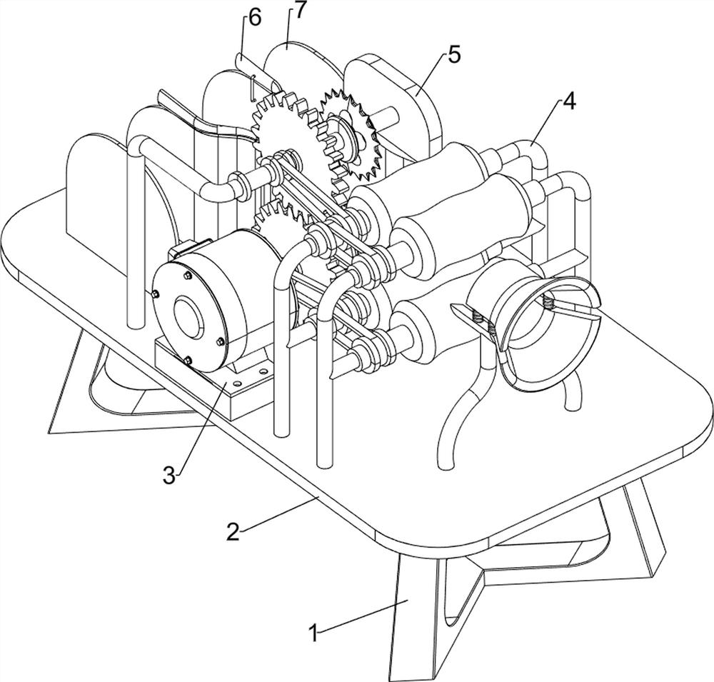
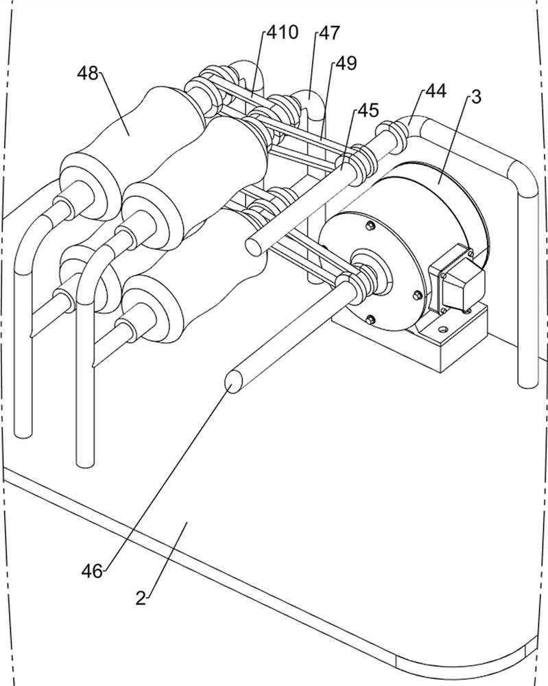
[0022] A cable core recovery separator, such as Figure 1-5 As shown, it includes a fixed bracket 1, a worktable 2, a motor 3, a transmission mechanism 4 and a cutting mechanism 5. The fixed bracket 1 is provided with a worktable 2, a motor 3 is installed on the front side of the top of the worktable 2, and a right side of the top of the worktable 2 is installed. A transmission mechanism 4 is provided on the side, and a cutting mechanism 5 is provided in the middle of the top side of the worktable 2 , and the cutting mechanism 5 cooperates with the transmission mechanism 4 .

[0023] Waste cables are harmful to the social environment and need to be recycled for a second time. However, the process of manually separating cables is cumbersome and complicated, and the separation speed is slow. This equipment can reduce the burden on workers. First, people insert the cables into the transmission mechanism 4, and then start the motor. 3. The rotation of the output shaft of the motor...

Embodiment 2

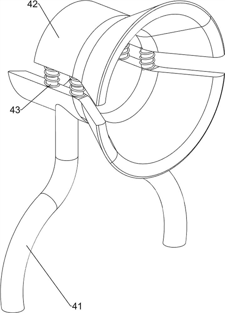
[0029] On the basis of Example 1, as figure 1 and Figure 5 As shown, it also includes a separation column 6 and a transmission isolation plate 7 , a transmission isolation plate 7 is symmetrically arranged on the left side of the top of the workbench 2 , and a separation column 6 is arranged on the inner top of the transmission isolation plate 7 .

[0030]After people insert the cable, start the motor 3, and when the cable starts to be divided, the separation columns 6 on the front and rear sides are inserted into the front and rear sides of the cable respectively. The inner cores are separated, the cable shell falls into the two transmission isolation plates 7, and the cable inner core falls between the two transmission isolation plates 7. If people still need to cut and separate the cables, they can continue to insert the cables. The motor 3 can be turned off for cutting. After the cutting knife 53 stops moving, people collect the cable cores. If the device needs to be use...


PUM


Abstract

The invention relates to a recovery separator, in particular to a cable core recovery separator. The invention provides a cable core recovery separator capable of automatic cutting and rapid separation of cables. A cable core recovery separator includes a fixed bracket, a workbench, a motor, a transmission mechanism, a cutting mechanism, etc.; a workbench is arranged on the fixed bracket, a motor is installed on the front side of the top of the workbench, and a transmission system is installed on the right side of the top of the workbench The middle part of the top side of the worktable is provided with a cutting mechanism, and the cutting mechanism cooperates with the transmission mechanism. The invention drives the first rotating shaft and the second rotating shaft to rotate through the operation of the motor, thereby driving the four soft rollers to roll, the four soft rollers roll and contact the cable to generate friction, and the friction force makes the cable gradually push in, so that the cable can move automatically. The effect is that there are four first telescopic components connected between the upper and lower splints of the arc-shaped splint, so that it can be adjusted according to the size of the cable so that it is stable and not in place.

Description

technical field [0001] The invention relates to a recovery separator, in particular to a cable core recovery separator. Background technique [0002] Cables are materials for related transmission applications such as electricity and communications. Cables transmit electricity and network to every household, which brings great convenience to people. [0003] The waste cable is harmful to the social environment and needs to be recycled for the second time. Therefore, it is necessary to manually separate the outer shell and the inner core of the cable. However, the manual separation process is cumbersome and complicated, the separation speed is slow, and it is time-consuming and labor-intensive, thus increasing the labor costs of workers. burden. [0004] Therefore, it is urgent to develop a cable core recovery separator that can automatically and quickly separate the cables. SUMMARY OF THE INVENTION [0005] In order to overcome the cumbersome and slow shortcomings of man...

Claims


Application Information

Patent Timeline
Patent Type & Authority Patents(China)
IPC IPC(8): B26D1/14B26D5/08B26D7/02B26D7/06H01B15/00
CPCB26D1/14B26D5/086B26D7/02B26D7/06H01B15/00Y02W30/82
Inventor 凌步顺
Owner 国网湖北省电力有限公司黄石供电公司
Why Eureka
Try Eureka