
Safety ring mounting device

An installation device and a safe and healthy technology, which is applied in the direction of display devices, instruments, padlocks, etc., can solve the problems of long replacement cycle of distribution line installation and construction, frequent changes of line equipment, hidden dangers of circuit operation, etc., to solve the problem of long replacement cycle, Improve safety and reliability, reduce the effect of aging damage

Inactive Publication Date: 2021-03-12
GUANGDONG POWER GRID CO LTD +1
View PDF8 Cites 0 Cited by
  • Summary
  • Abstract
  • Description
  • Claims
  • Application Information

AI Technical Summary

Problems solved by technology

[0003] However, due to the continuous improvement and adjustment of the power grid structure, the frequent changes of line equipment, the installation ring needs to be replaced frequently, and the outdoor equipment installation ring is easily aged and damaged due to long-term environmental and other factors. The installation ring used by the current power distribution equipment needs special printing machines , under the influence of the external complex environment, it is easy to cause problems such as missing and inaccurate installation and construction rings, and there are large hidden dangers in circuit operation if they are not replaced in time or the replacement cycle is long, which will cause great damage to the operation and maintenance of power distribution lines. risk
[0004] Therefore, at present, it is necessary to carry out structural transformation on the installation and construction ring of power distribution equipment to solve the problems of long replacement cycle, easy aging and damage, and inaccuracy of distribution line installation and construction ring, improve the safety and reliability of equipment operation, and bring great benefits to the safe production of electric power. to protect

Method used


Image

  • Safety ring mounting device
  • Safety ring mounting device
  • Safety ring mounting device

Examples


Embodiment 1

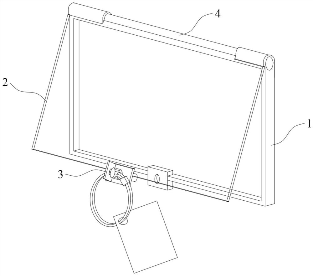
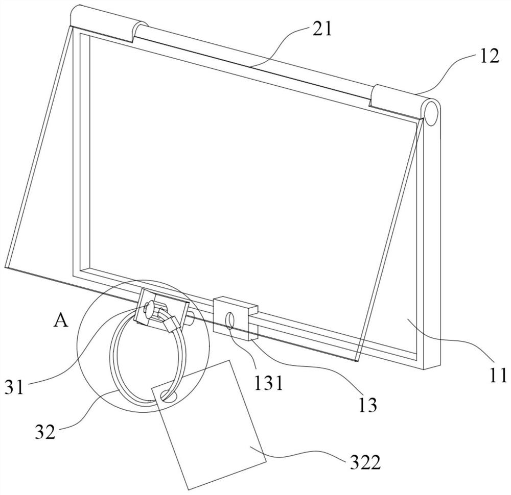
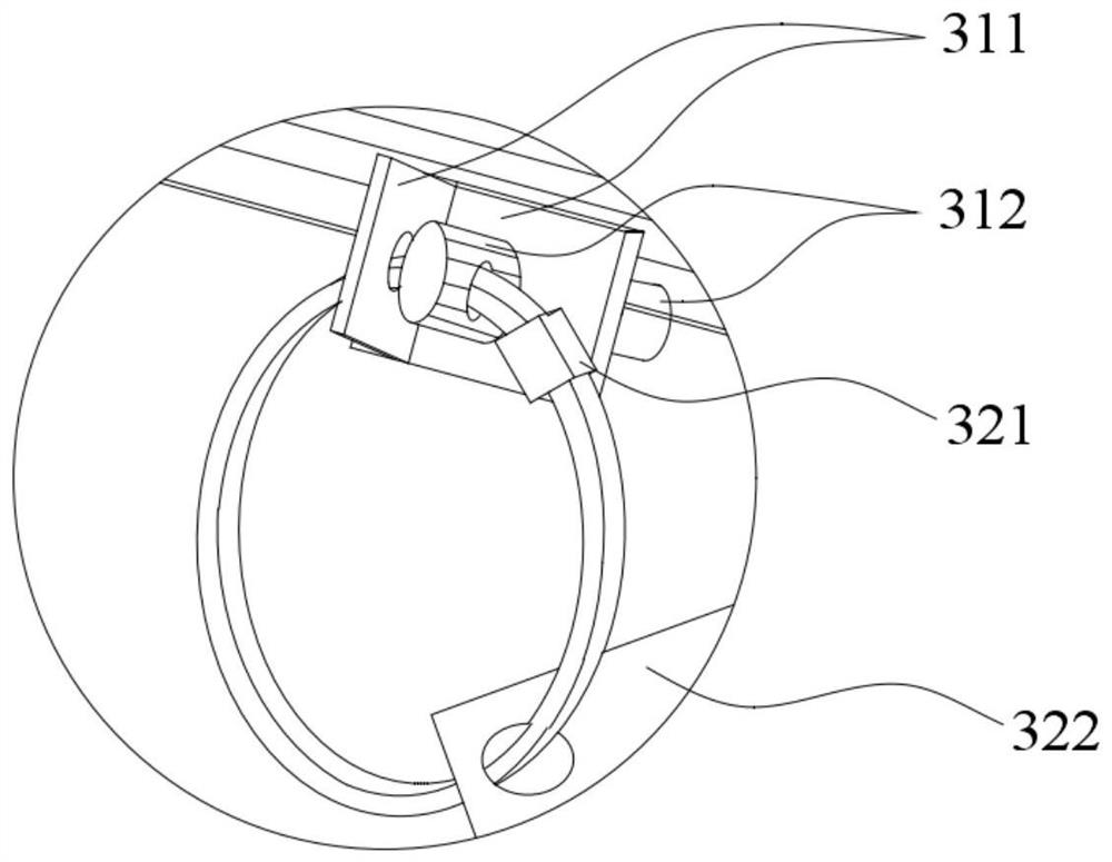
[0036] see Figure 1 to Figure 3 , this embodiment provides a safety and health ring installation device, including a bottom plate 1, a cover plate 2 and a locking mechanism 3, one side of the bottom plate 1 is provided with a receiving groove 11, and a sealing ring is arranged around the notch of the receiving groove 11 to accommodate The groove 11 is used to accommodate the safety ring. The cover plate 2 is made of a transparent material. The cover plate 2 is rotatably connected to the base plate 1 and can cover the accommodation groove 11. When the cover plate 2 covers the accommodation groove 11, it will be attached to the seal ring, and the safety ring abuts against the sealing ring at the notch of the receiving groove 11 , and the locking mechanism 3 is arranged on the cover plate 2 and can lock the cover plate 2 on the bottom plate 1 .

[0037] In the safety ring installation device of the present invention, a closed structure for placing the safety ring is formed by th...

Embodiment 2

[0051] The second embodiment discloses a safety ring installation device, the structure of which is basically the same as that of the first embodiment. The device mainly includes a bottom plate 1, a cover plate 2 and a locking mechanism 3. One side of the bottom plate 1 is provided with a receiving groove 11, and a sealing ring is arranged around the notch of the receiving groove 11, and the receiving groove 11 is used for accommodating the safety ring. The cover plate 2 is made of a transparent material, and is rotatably connected to the bottom plate 1, and can cover the accommodation groove 11. When the cover plate 2 covers the accommodation groove 11, it is attached to the sealing ring, and the safety ring is attached to the accommodation groove 11 Seal ring at the notch. The locking mechanism 3 is arranged on the cover plate 2 and can lock the cover plate 2 on the bottom plate 1 . The above-mentioned structural arrangement is basically the same as that in the first embod...


PUM


Abstract

The invention relates to the technical field of safety ring installation, in particular to a safety ring mounting device. The safety ring mounting device comprises a bottom plate, a cover plate and alocking mechanism, wherein a containing groove used for containing a safety ring is formed in one side of the bottom plate, a sealing ring is arranged at a groove opening of the containing groove, thecover plate is rotationally connected to the bottom plate and can seal the containing groove, the cover plate is attached to the sealing ring when sealing the containment groove, and the locking mechanism can lock the cover plate on the bottom plate. According to the safety ring mounting device, the bottom plate provided with the containing groove and the cover plate connected to the bottom plateform a closed structure used for containing the safety ring, the influence of the external environment is effectively avoided, the sealing performance is enhanced through the sealing ring, the degreeof easy aging and damage is reduced, the cover plate is rotationally connected to the bottom plate to achieve the openable and closable function, the safety ring can be replaced and modified by turning over the cover plate, the operation is simple, the safety ring is convenient to replace in time, meanwhile, the cover plate can be locked on the bottom plate through the locking mechanism, random replacement is prevented, the accuracy of the safety ring is guaranteed, and the safety and reliability of equipment operation are improved.

Description

technical field [0001] The invention relates to the technical field of safety ring installation, in particular to a safety ring installation device. Background technique [0002] There are a wide variety of safety warning signs in the power system and they are used in various working environments. Among them, the distribution network safety and construction environment can standardize the operation and management of the distribution network, strengthen the safety warning signs of the distribution network equipment, prevent wrong operations, and ensure the safety of power production. etc. play an important role. [0003] However, due to the continuous improvement and adjustment of the power grid structure, the line equipment changes frequently, the installation ring needs to be replaced frequently, and the outdoor equipment installation ring is easily aged and damaged due to long-term environmental and other factors. The installation ring used by the current power distributio...

Claims


Application Information

Patent Timeline
Patent Type & Authority Applications(China)
IPC IPC(8): E05B67/00E05B15/00G09F7/00
CPCE05B15/00E05B67/00G09F7/00
Inventor 林少伟蔡佳佳黄钢刘晓枫王德中龚传郧黄子建蔡依麟胡磊陈昊妍廖丽阳孔祥美邱泽鹏郑淳锋蓝祧泽陈子隆王佳秋唐康康廖悦凯马梓阳陈晓纯连明畴李茵李楠
Owner GUANGDONG POWER GRID CO LTD
Learn More