
A buck-boost circuit and its control method

A buck-boost circuit and control method technology, which is applied in the direction of control/regulation systems, electrical components, and adjustment of electrical variables, etc., can solve the problems of low working efficiency of Buck-Boost power converters, large effective current value of power loops, and low working efficiency. Low-level problems, to achieve the effect of improving high-efficiency output, reducing conduction loss and switching loss, and reducing the number of switching times

Active Publication Date: 2022-01-14
MORNSUN GUANGZHOU SCI & TECH
View PDF8 Cites 0 Cited by
  • Summary
  • Abstract
  • Description
  • Claims
  • Application Information

AI Technical Summary

Problems solved by technology

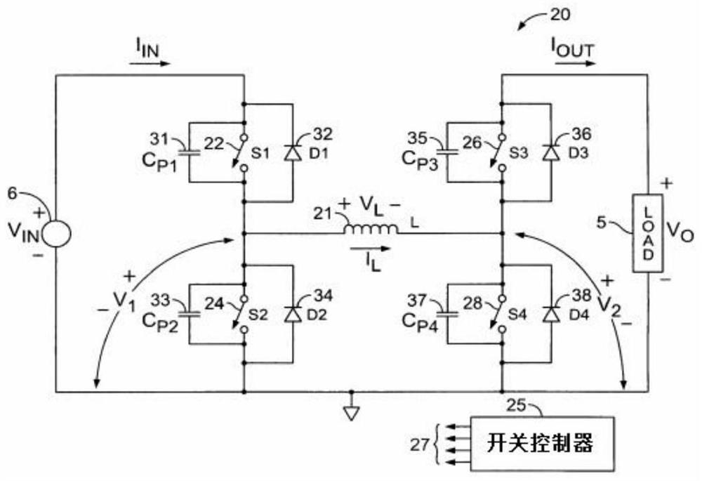
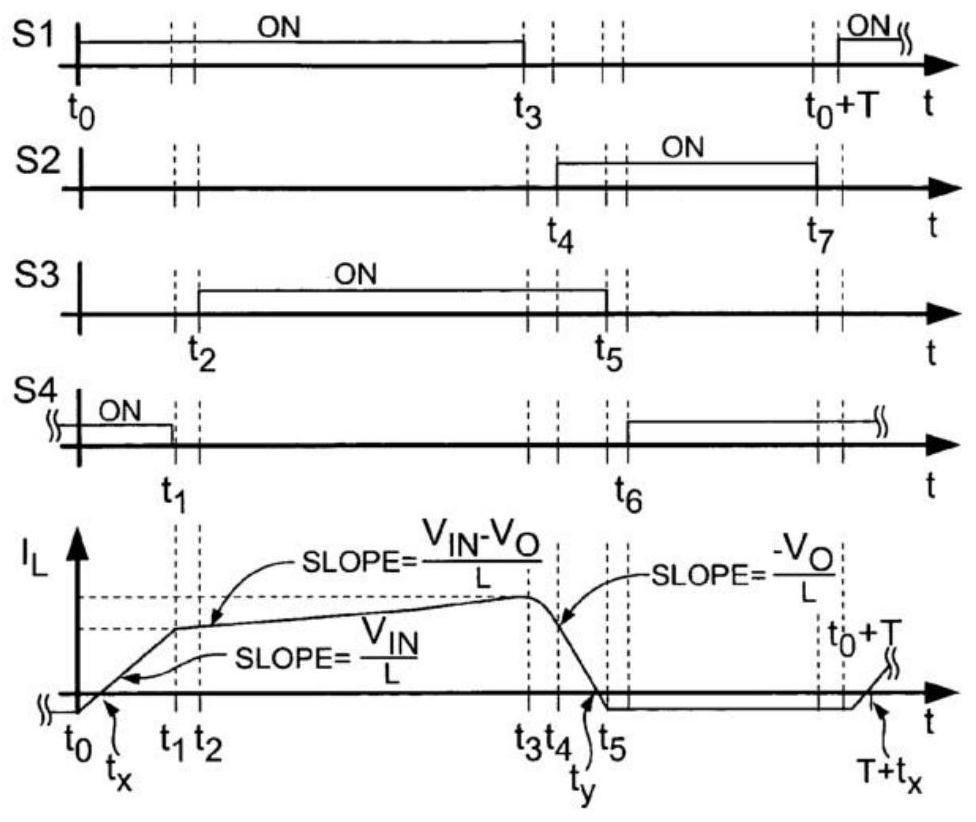
When the input voltage Vin is much higher than the output voltage Vo, or when the load is light at the same time, due to the existence of the input phase (that is, the time period from t0 to t1), the effective current value of the power loop of the Buck-Boost power converter is relatively large, And because the switching tubes S1, S2, S3 and S4 need to be switched once in each cycle, the working efficiency of the Buck-Boost power converter is not high; similarly, when the input voltage Vin is lower than the output voltage Vo more, or at the same time When the load is light, due to the existence of the output stage (that is, the time period from t4 to t5), the effective current value of the power loop of the Buck-Boost power converter is relatively large, and because each cycle of the switching tubes S1, S2, S3 and S4 Both need to be switched once, so the working efficiency of the Buck-Boost power converter is not high
[0006] Depend on image 3 and Figure 4 It can be seen that the existing control strategy of the Buck-Boost power converter is not suitable for the scenario where the input voltage and the output voltage differ greatly, which will lead to very low working efficiency

Method used


Image

  • A buck-boost circuit and its control method
  • A buck-boost circuit and its control method
  • A buck-boost circuit and its control method

Examples


Embodiment Construction

[0053] Figure 5 It is a schematic diagram of the buck-boost circuit of the present invention, such as Figure 5 As shown, the buck-boost circuit includes a voltage conversion circuit and a controller.

[0054] The voltage conversion circuit includes an input terminal for receiving an input voltage Vin, an output terminal for generating an output voltage Vo, a common power ground GND, a switch component and an inductor L. Among them, the switch assembly is composed of switch tube Q1, switch tube Q2, switch tube Q3 and switch tube Q4, switch tube Q1, switch tube Q2, switch tube Q3 and switch tube Q4 can be MOS tube, triode or IGBT and other types of switch tubes .

[0055] The drain of the switching tube Q1 is used as the input terminal of the voltage conversion circuit for connecting the input voltage Vin; the source of the switching tube Q1 and the drain of the switching tube Q2 are respectively connected to the first end SW1 of the inductor L; the source of the switching t...


PUM


Abstract

The invention relates to the field of switching power supplies, and discloses an ultra-wide-voltage input soft switch buck-boost circuit and a control method thereof. The controller determines the load, clamping stage, and switching frequency according to the relationship between the input voltage Vin and the output voltage Vo. Switching between multiple working modes realizes that the buck-boost circuit can still work efficiently under a wide input voltage.

Description

technical field [0001] The invention relates to the field of switching power supplies, in particular to a wide-voltage input soft switch buck-boost circuit and a control method thereof. Background technique [0002] Please refer to figure 1 , which is a well-known buck-boost circuit, the input voltage Vin can be higher than, lower than or equal to the output voltage Vo, and its working mode is that the switch tube S1 and the switch tube S4 are turned on at the same time, and then the switch tube S2 and the switch tube are turned off after being turned off. The tube S3 is turned on at the same time, so the cycle works, and the output voltage is stabilized by adjusting the duty cycle. However, the effective current value of the power loop is large and hard switching, so the loss is large and the efficiency is low. [0003] The application number is 10 / 885,827, and the U.S. patent titled "Buck-Boost DC-DC switching power conversion" is in figure 1 Optimizing the control metho...

Claims


Application Information

Patent Timeline
Patent Type & Authority Patents(China)
IPC IPC(8): H02M3/158
CPCH02M3/1582Y02B70/10
Inventor 卢鹏飞
Owner MORNSUN GUANGZHOU SCI & TECH
Learn More