
Circular shaft moving anti-rotation mechanism

An anti-rotation and anti-rotation structure technology, applied in the field of anti-rotation mechanism, can solve problems such as thimble wear and affect motion accuracy, and achieve the effect of preventing rotation

Pending Publication Date: 2021-03-16
长园半导体设备(珠海)有限公司
View PDF0 Cites 0 Cited by
  • Summary
  • Abstract
  • Description
  • Claims
  • Application Information

AI Technical Summary

Problems solved by technology

[0003] But in actual use, the thimble will rotate relative to the base, which will cause the thimble to wear and affect the movement accuracy

Method used


Image

  • Circular shaft moving anti-rotation mechanism
  • Circular shaft moving anti-rotation mechanism
  • Circular shaft moving anti-rotation mechanism

Examples


Embodiment Construction

[0021] The technical solutions in the embodiments of the present invention will be clearly and completely described below with reference to the accompanying drawings in the embodiments of the present invention. Obviously, the described embodiments are only a part of the embodiments of the present invention, but not all of the embodiments. Based on the embodiments of the present invention, all other embodiments obtained by those of ordinary skill in the art without creative efforts shall fall within the protection scope of the present invention.

[0022] It should be noted that when a component is referred to as being "fixed to" another component, it may be directly on the other component or there may also be another intermediate component through which it is fixed. When a component is said to be "connected" to another component, it can be directly connected to the other component or there may be another intermediate component present at the same time. When a component is said ...


PUM


Abstract

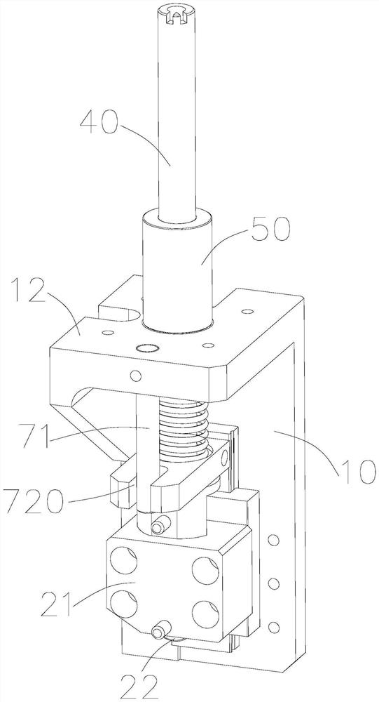
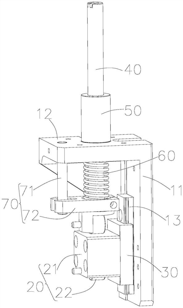
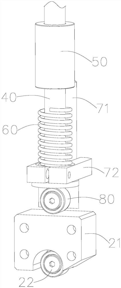
The invention discloses a circular shaft moving anti-rotation mechanism comprising a base, a moving shaft, an elastic piece and an anti-rotation structure. The moving shaft, the elastic piece and theanti-rotation structure are installed on the base; the two ends of the elastic piece abut against the base and the moving shaft respectively to enable the moving shaft to reciprocate relative to the base; the anti-rotation structure comprises an anti-rotation shaft and a limiting block; the anti-rotation shaft and the limiting block are respectively fixed to the base and the moving shaft; the limiting block is provided with a limiting groove; and the anti-rotation shaft is located in the limiting groove to prevent the moving shaft to rotate relative to the base. By means of the design, when the moving shaft reciprocates relative to the base, the limiting block moves up and down along the anti-rotation shaft, movement of the moving shaft is not affected, and when the moving shaft rotates, the limiting block cannot rotate as the edge of the limiting groove abuts against the anti-rotation shaft, the moving shaft does not rotate, and the effect of preventing rotation is achieved.

Description

technical field [0001] The invention relates to an anti-rotation mechanism, in particular to a circular shaft movement anti-rotation mechanism. Background technique [0002] In the mold equipment, after the product is formed, the product needs to be ejected from the mold with an ejector pin. After the product is ejected, the ejector pin needs to leave the cavity to reset and wait for the next ejection. Therefore, during the injection molding process, the thimble needs to continuously move up and down relative to the base. [0003] However, in actual use, the thimble will rotate relative to the base, which will cause the thimble to wear and affect the movement accuracy. SUMMARY OF THE INVENTION [0004] In order to overcome the deficiencies of the prior art, one of the objectives of the present invention is to provide an anti-rotation mechanism for moving a circular shaft. [0005] One of the objects of the present invention adopts the following technical scheme to reali...

Claims


Application Information

Patent Timeline
IPC IPC(8): B29C45/40
CPCB29C45/401
Inventor 王慧蔡奇陵
Owner 长园半导体设备(珠海)有限公司
Learn More