
Compact material supporting mechanism

A compact and material-holding technology, which is applied in the direction of forming tools, metal processing equipment, manufacturing tools, etc., can solve the problems of inability to lift parts or upper molds, large space, etc., and achieve simple structure, low cost, and prevent rotation Effect

Inactive Publication Date: 2014-03-26
TIANJIN MOTOR DIES
View PDF0 Cites 0 Cited by
  • Summary
  • Abstract
  • Description
  • Claims
  • Application Information

AI Technical Summary

Problems solved by technology

It is not possible to use related cylinders such as lifters to lift up, because the lifter and other related cylinders require a large space and necessary pipelines, and due to space constraints, it is impossible to lift the workpiece or upper mold

Method used


Image

  • Compact material supporting mechanism
  • Compact material supporting mechanism

Examples


Embodiment Construction

[0018] A specific embodiment is enumerated below in conjunction with the accompanying drawings to further illustrate the invention.

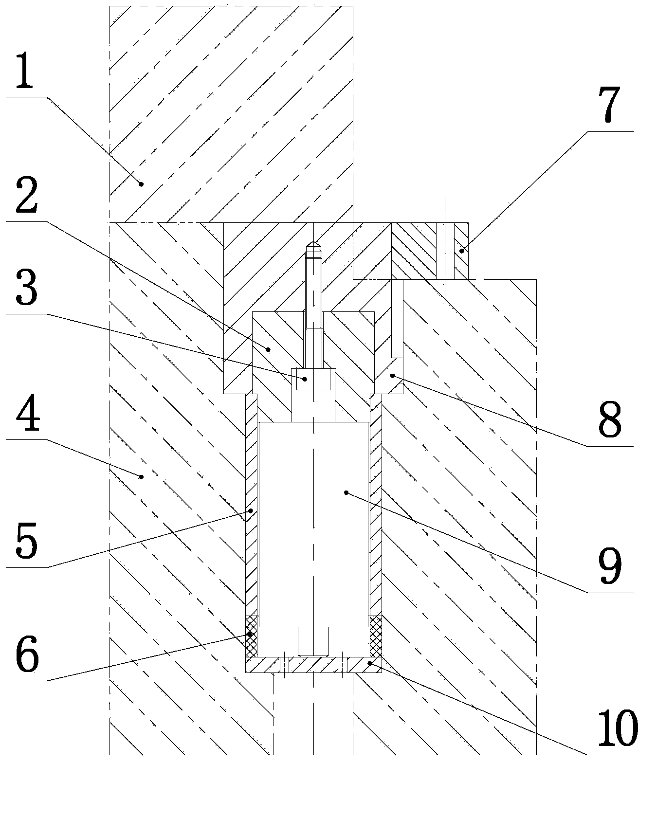
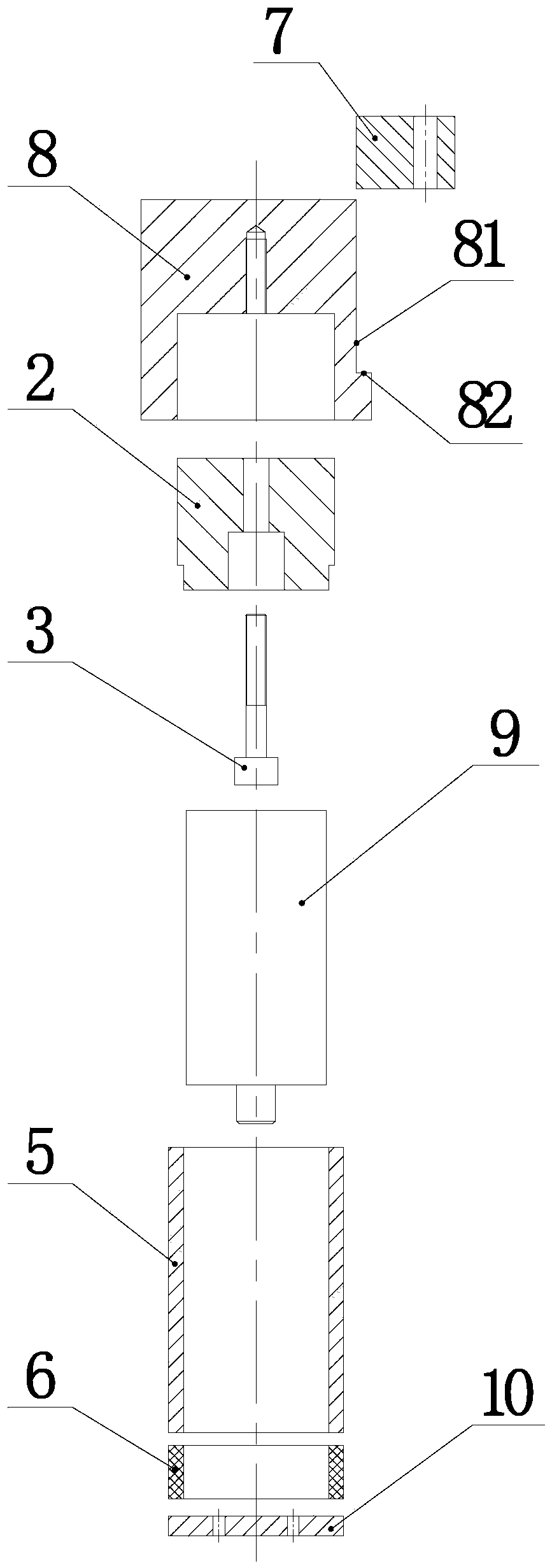
[0019] Such as figure 1 , figure 2 As shown, this embodiment is a compact supporting mechanism, which includes a supporting block 8 , a guide sleeve 5 , a guide post 2 , a nitrogen cylinder 9 and a spacer 10 . This mechanism is installed in the cavity of the lower mold 4 of the automobile mould. The purpose is to hold up the upper mold 1 through this mechanism; The supporting block 8 is connected with an interference fit between the middle shaft hole and the outer peripheral surface of the guide sleeve 5, and the lower shaft hole is connected with the lower end surface.

[0020] A blind hole is provided at the symmetrical center of the bottom end surface of the supporting block 8; the outer circumference of the supporting block 8 is provided with two mutually perpendicular intersecting planes, wherein the plane parallel to the central axis of...


PUM


Abstract

The invention provides a compact material supporting mechanism. The compact material supporting mechanism comprises a material supporting block, a guide sleeve, a guide column, a cylinder and a cushion block; the symmetry center of the bottom end surface of the material supporting block is provided with a blind hole; the central axis of the guide sleeve is provided with a cylindrical through hole; the guide column is in a stepped shaft shape and comprises the large shaft section and the small shaft section; the large shaft section of the guide column is nested in the blind hole of the material supporting block; the small shaft section of the guide column is matched and connected with the cylindrical through hole of the guide sleeve in a sliding mode; the cylinder is nested in the guide sleeve; the bottom end surface of the cylinder is in contact connection with the bottom end surface of the guide column; the cushion block is of a disk structure; the upper end surface of the cushion block is in contact connection with the end surface of a piston rod of the cylinder. According to the compact material supporting mechanism, the structure is simple, compact and reasonable, the cost is low, and the accurate guiding, anti-rotation and limiting can be achieved.

Description

technical field [0001] The invention belongs to the field of mold design and manufacture of automobile cover parts, and in particular relates to a material supporting mechanism used in a narrow space to lift parts. Background technique [0002] During the design and manufacture of automobile panel molds, many molds need to lift the parts or upper molds, and the space area is small. It is not possible to use related cylinders such as lifters to lift up, because the related cylinders such as lifters require a large space and necessary pipelines to lift up, and due to space constraints, the workpiece or upper mold cannot be lifted. Contents of the invention [0003] The problem to be solved by the invention is to provide a compact material supporting mechanism with simple, compact and reasonable structure, low cost, high guiding precision and rotation prevention. [0004] In order to solve the above technical problems, the technical solution adopted by the invention is: a co...

Claims


Application Information

Patent Timeline
IPC IPC(8): B21D37/14
Inventor 郭迎亮彭鹏
Owner TIANJIN MOTOR DIES
Learn More