
Piston pin hole lining structure

A technology of piston pin hole and piston pin, applied in the direction of piston, engine lubrication, machine/engine, etc., can solve the problems of increasing the surface temperature and specific pressure of the piston pin hole, destroying the lubricating oil film, breaking, etc., to improve reliability and reliability. Service life, reduced risk of cracking, increased contact area effect

Active Publication Date: 2022-06-21
BEIJING INSTITUTE OF TECHNOLOGYGY
View PDF23 Cites 0 Cited by
  • Summary
  • Abstract
  • Description
  • Claims
  • Application Information

AI Technical Summary

Problems solved by technology

[0003] The technical problem to be solved by a kind of piston pin hole bushing structure disclosed by the present invention is: (1) to solve the piston pin hole bushing installed in the piston pin hole The problem of rotation and shedding will occur under the working conditions of high temperature, high load and high frequency movement; (2) Solve the problem that the surface temperature and specific pressure of the piston pin hole will increase due to the increase of the burst pressure, which will destroy the lubricating oil film and cause the piston pin to bite (3) Solve the problem that the piston pin hole of the engine piston will produce huge stress under the joint action of the explosion pressure and the piston pin during the working process, resulting in fracture and reducing the service life of the piston

Method used


Image

  • Piston pin hole lining structure
  • Piston pin hole lining structure

Examples


Embodiment Construction

[0022] In order to better illustrate the purpose and advantages of the present invention, the content of the invention will be further described below with reference to the accompanying drawings and examples.

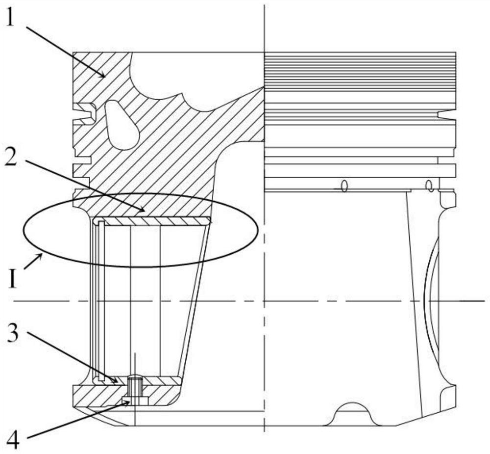
[0023] like figure 1 As shown, a piston pin hole bushing structure disclosed in this embodiment is provided on the piston 1 with a piston pin hole 2 for carrying the piston pin. A piston pin hole bushing 3 is installed in the piston pin hole 2 , and the piston pin hole bushing 3 is installed into the piston pin hole 2 through an interference fit. A countersunk head threaded through hole is opened on the back side of the lowest point of the piston pin hole 2, and a hollow fixing bolt 4 is installed through the countersunk head threaded through hole. between the inner surfaces to ensure that the normal operation of the piston pin is not affected. The piston 1 and the piston pin hole bushing 3 are fixed together by the thread on the hollow fixing bolt 4 . The hollow str...


PUM


Abstract

The invention discloses a piston pin hole lining structure, and belongs to the technical field of internal combustion engine part structures. The piston and the piston pin hole bush are in threaded connection, the hollow fixing bolt extends into the piston pin hole bush, movement of the piston pin hole bush is limited, and the piston pin hole bush is prevented from rotating in the working process of an engine; and the piston pin hole bushing additionally arranged in the piston pin hole is prevented from rotating and falling off under the working conditions of high temperature, high load and high-frequency motion. The hollow fixing bolt is adopted for providing a channel for splashing lubricating oil, lubrication between the piston pin and the piston pin hole lining is enhanced, and the situation that the piston pin is meshed is prevented. The special-shaped structure is added to the inner ring of the piston pin hole bush, so that the piston pin is well attached to the piston pin hole bush in the working state, the contact area of the piston pin and the piston pin hole bush is increased, the surface stress of a piston pin hole is reduced, abrasion is reduced, the cracking risk of the piston pin hole is reduced, the reliability of the piston is improved, and the service life of the piston is prolonged.

Description

technical field [0001] The invention belongs to the technical field of internal combustion engine parts structures, and relates to a piston pin hole bushing structure. Background technique [0002] High power density diesel engine is the main development direction of vehicle power plant. The main energy conversion method in diesel engine is crank connecting rod mechanism. The burst pressure generated by combustion acts on the top of the piston to drive the piston, and the piston is connected to the small end of the connecting rod through the piston pin. The connecting rod big end is then connected to the crankshaft. As the piston reciprocates within the cylinder, the crankshaft rotates to generate drive torque. With the continuous improvement of engine power and speed, the maximum combustion pressure carried by the top surface of the diesel piston has reached more than 22MPa. The piston pin hole will generate huge stress and obvious deformation under the combined action of...

Claims


Application Information

Patent Timeline
Patent Type & Authority Applications(China)
IPC IPC(8): F02F3/00F01M9/00F01M9/06
CPCF02F3/00F01M9/00F01M9/06
Inventor 郭镇瑶原彦鹏张卫正靳爽曹子聪
Owner BEIJING INSTITUTE OF TECHNOLOGYGY
Learn More