Escape fireproof window with anti-theft function
A fireproof window and function technology, applied in the field of escape fireproof windows, can solve the problems of shortened escape time, high maintenance cost, closing windows, etc., and achieve the effect of improving the anti-theft effect, preventing the spread of fire, and improving the escape effect.
- Summary
- Abstract
- Description
- Claims
- Application Information
AI Technical Summary
Problems solved by technology
Method used
Image
Examples
specific Embodiment approach 2
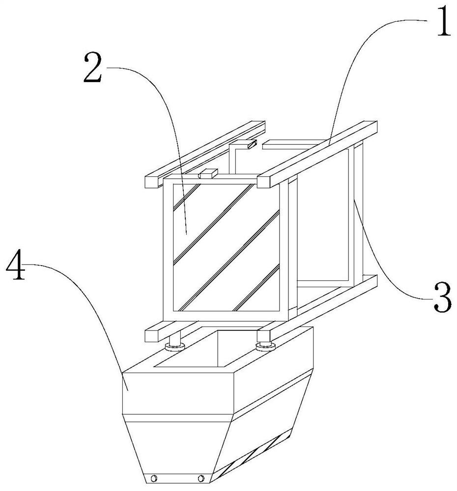
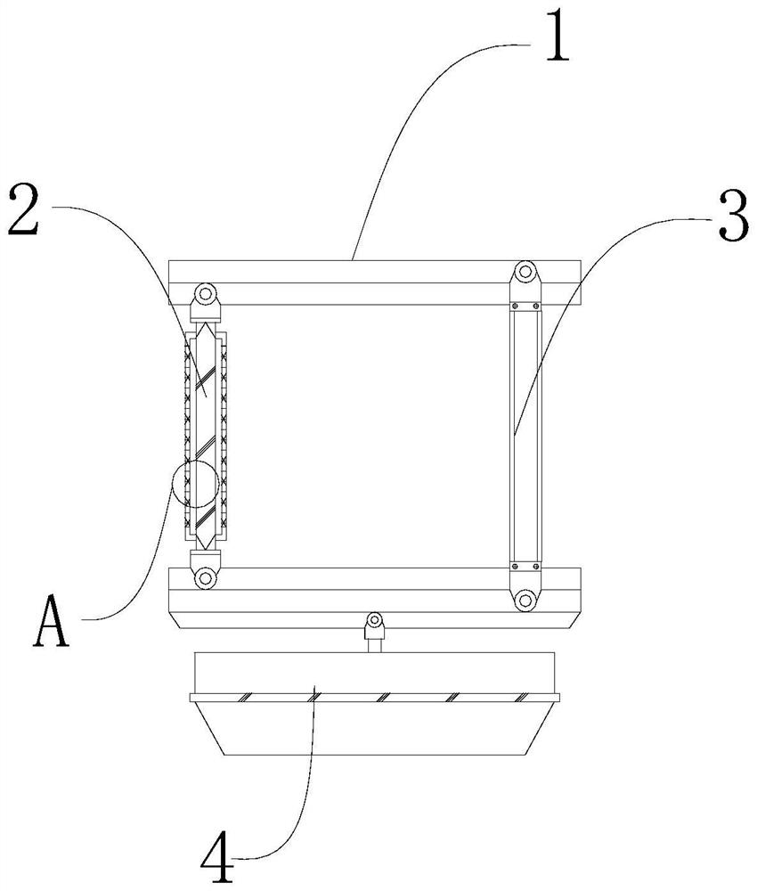
[0041] see Figures 1 to 14 Among them, in the embodiment of the present invention, an escape fireproof window with an anti-theft function, the escape cabin 4 includes: a connecting roller 11 and a cabin body 12, the bottom of which is fixedly connected with the cabin body 12, and the cabin body 12 is a semi-open top design There is an opening, and connecting rollers 11 are provided on the left and right sides of the edge of the opening, and slideways are provided at the bottom of the two tracks 1 below. , enter the escape cabin 4 below by turning over the locking frame 3, then move the fireproof window 2 into the locking frame 3 for locking, and then move the locked fireproof window to the last place where the track is installed Close, block the fire, prevent the fire from spreading, and then push the escape cabin 4 to move to the outermost side in the slideway, which is convenient for firefighters to rescue and achieve better escape effect.
[0042] Further preferably, an e...
specific Embodiment approach 3
[0045] see Figures 1 to 14 Among them, in the embodiment of the present invention, an escape fireproof window with anti-theft function, the upper end of the extruder 16 connecting pipe is connected with the air pipe 22, and a channel is opened inside the inner wall above the right side of the cabin body 12. A drive rotor 21 is movably connected to the inner wall of the channel, and a card slot 23 is fixedly connected to the surface of the drive rotor 21 . There is a rotor 18, and a deflector 19 is fixedly connected directly below the rotor 18. At the same time, an arc-shaped protrusion is fixedly connected obliquely above the rotor 18. The transmission rotor 21 and the surface of the rotor 18 mesh with each other. , the air pressure is formed to be sent out through the air pipe 22, the air pressure blown out of the air pipe is blown to the slot 23 of the transmission rotor 21, the air pressure drives the transmission rotor 21 to rotate clockwise, and the transmission rotor 21...
PUM
 Abstract
Description
Claims
Application Information
 - R&D
- Intellectual Property
- Life Sciences
- Materials
- Tech Scout
- Unparalleled Data Quality
- Higher Quality Content
- 60% Fewer Hallucinations
Browse by: Latest US Patents, China's latest patents, Technical Efficacy Thesaurus, Application Domain, Technology Topic, Popular Technical Reports.
© 2025 PatSnap. All rights reserved.Legal|Privacy policy|Modern Slavery Act Transparency Statement|Sitemap|About US| Contact US: help@patsnap.com


