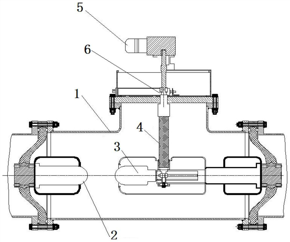
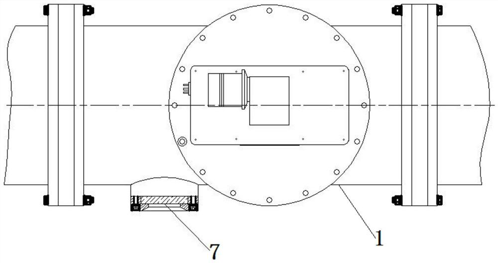
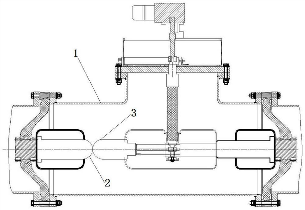
Isolating switch

A technology of isolating switch and moving contact, applied in the direction of air switch parts, etc., can solve the problems of limited application scope, single function, limited function, etc., to achieve the effect of convenient use

Pending Publication Date: 2021-03-16
MEASUREMENT CENT OF GUANGDONG POWER GRID CO LTD
View PDF0 Cites 0 Cited by
  • Summary
  • Abstract
  • Description
  • Claims
  • Application Information

AI Technical Summary

Problems solved by technology

[0002] The isolating switch is a switching device used to connect or cut off the circuit; at present, most of the isolating switches in China are closed structures, and the internal structure cannot be clearly observed from the outside, the function is single, and the functions are limited, which limits its application range

Method used


Image

  • Isolating switch
  • Isolating switch
  • Isolating switch

Examples


Embodiment Construction

[0026] The following will clearly and completely describe the technical solutions of the embodiments of the present application with reference to the accompanying drawings. Apparently, the described embodiments are part of the embodiments of the present application, not all of them. Based on the embodiments in the embodiments of the present application, all other embodiments obtained by persons of ordinary skill in the art without making creative efforts belong to the protection scope of the embodiments of the present application.

[0027] In the description of the embodiments of the present application, it should be noted that the terms "center", "upper", "lower", "left", "right", "vertical", "horizontal", "inner", "outer " and other indicated orientations or positional relationships are based on the orientations or positional relationships shown in the drawings, and are only for the convenience of describing the embodiments of the present application and simplifying the descr...


PUM


Abstract

The invention discloses an isolating switch, which comprises a shell box body, a static contact, a moving contact, a driving device and a displacement indicating device; the static contact is fixedlyarranged in the shell box body; the moving contact is movably arranged in the shell box body along the same straight line direction as the static contact; the driving device is connected with the moving contact and used for driving the moving contact to move in the direction close to the static contact or away from the static contact; and the displacement indicating device is arranged on the shellbox body and is used for indicating the moving displacement of the moving contact after moving. The motor and the moving contact are connected through an insulating rod, movement of the moving contact is directly controlled, the displacement indicating end is arranged on the insulating rod, the position of the moving contact can be checked in real time through the shell box body, and use of the isolating switch is facilitated.

Description

technical field [0001] The present application relates to the field of isolating switches of electric equipment, in particular to an isolating switch. Background technique [0002] The isolating switch is a switching device used to connect or cut off the circuit. At present, most of the isolating switches in China are closed structures, and the internal structure cannot be clearly observed from the outside. The function is single and the functions are limited, which limits its application range. Contents of the invention [0003] In view of this, the purpose of the present application is to provide a disconnector that can visually display the moving distance of the movable contact in the disconnector. [0004] In order to achieve the above-mentioned technical purpose, the application provides a disconnector, including: an outer casing, a static contact, a moving contact, a driving device and a displacement indicating device; [0005] The static contact is fixedly installe...

Claims


Application Information

Patent Timeline
IPC IPC(8): H01H31/02H01H31/06
CPCH01H31/02H01H31/06
Inventor 张鼎衢宋强刘日荣孟庆亮陈峰
Owner MEASUREMENT CENT OF GUANGDONG POWER GRID CO LTD
Why Eureka
Try Eureka