NEAR 2Pi COMPTON CAMERA FOR MEDICAL IMAGING

A medical imaging and medical imaging system technology, applied in the field of medical imaging, can solve the problems of Compton cone ring offset, Compton angle uncertainty, etc.

Pending Publication Date: 2021-03-16
SIEMENS MEDICAL SOLUTIONS USA INC
View PDF18 Cites 0 Cited by
  • Summary
  • Abstract
  • Description
  • Claims
  • Application Information

AI Technical Summary

Problems solved by technology

Limited detector energy resolution leads to additional Compton angle uncertainty
Limited detector position resolution in both the scatter and trap layers leads to additional Compton cone offset

Method used


Image

  • NEAR 2Pi COMPTON CAMERA FOR MEDICAL IMAGING
  • NEAR 2Pi COMPTON CAMERA FOR MEDICAL IMAGING
  • NEAR 2Pi COMPTON CAMERA FOR MEDICAL IMAGING

Examples


Embodiment Construction

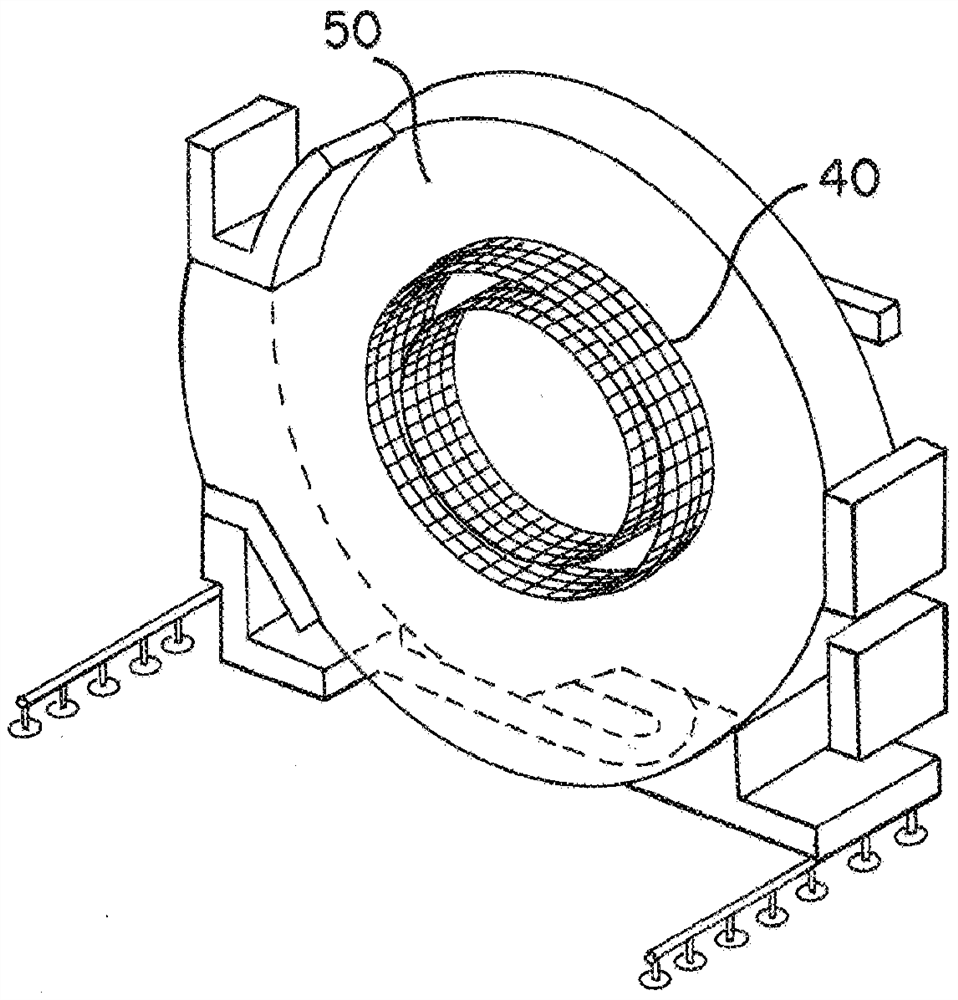
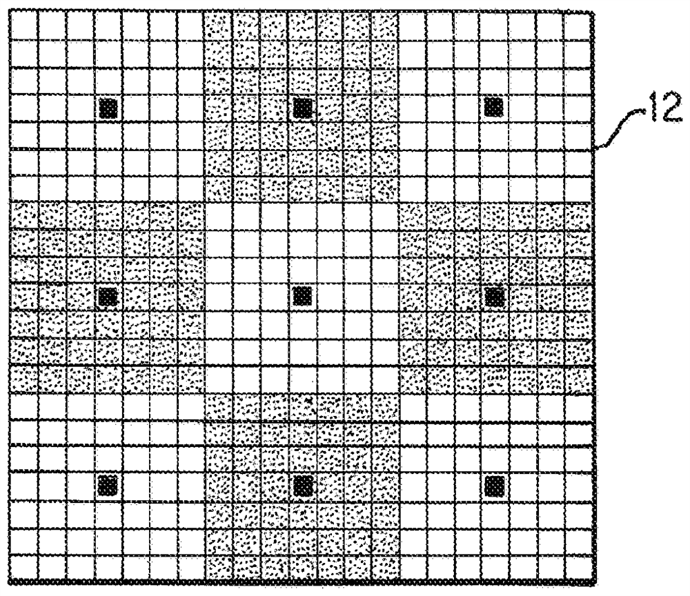
[0025] Figure 1-9 For multimodal compatible Compton cameras. Modular design to form Compton cameras for use with various other imaging modalities. Figure 11-15 For Compton cameras with slanted scatter detectors and / or near 2π trap detectors. Slanted scatter detectors and / or near 2π trap detectors for Figure 1-9 module, in other modules, or without modules. After summarizing the tilted scatter detector and / or near 2π trap detector embodiments, the description Figure 1-9 Compton camera. Figure 1-9 Many of the features and components of the Compton camera can be used later for Figure 11-15 Examples of tilted scatter detectors and / or near 2π trap detectors are described.

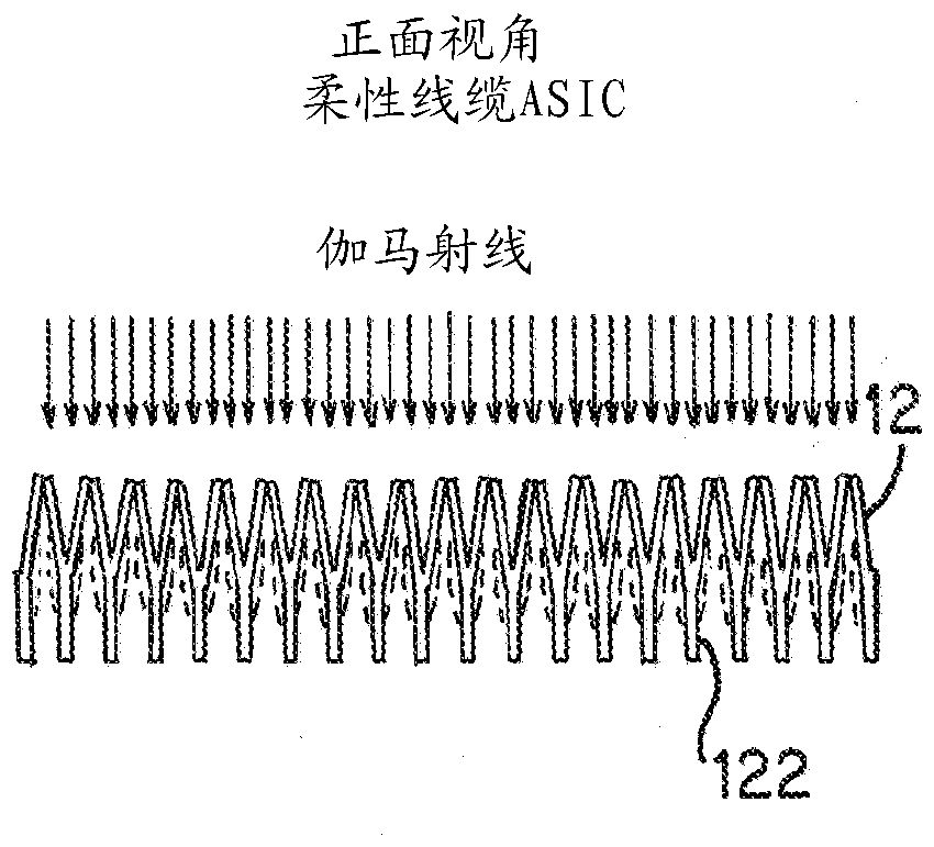
[0026] Slanted scatter detectors and / or near 2π trap detectors provide more efficient Compton cameras. Sensitivity ($) and / or image quality (IQ) can be improved. Synchronization and triggering limitations between modules can be avoided by trapping photons at a higher rate within the module. and f...


PUM


Abstract

To capture more emitted photons with a Compton camera, the scatter detector (12) is tilted (non-orthogonal angle) relative to a radial from the isocenter of the imaging system. The tilt creates a greater volume for scatter interaction. To capture more scatter photons, the catcher detector (13) is non-planar, such as a multi-faced detector at least partially surrounding a volume behind the scatterdetector (12). The tilted scatter detector (12) alone, the non-planar catcher detector (13) alone, or the tilted scatter detector (12) and the non-planar catcher detector (13) are used in the Comptoncamera.

Description

Background technique [0001] This embodiment relates to medical imaging using the Compton effect. The Compton effect allows higher imaging energies than that used for single photon emission computed tomography (SPECT). The Compton imaging system was constructed as a test platform, for example the scattering layer was assembled and then the trapper layer was mounted to the large frame. Electronics are connected to detect Compton-based events from the phantom's emissions. The Compton imaging system failed to address the design and constraint requirements for practical use in any commercial clinical setting. Current proposals lack the ability to integrate into imaging platforms in the clinic, or lack the design and constraint requirements (ie, flexibility and scalability) to address commercial and diagnostic needs. [0002] Compton cameras can have low sensitivity ($) and poor image quality (IQ). The absolute number of scattered photons in the scattering layer is low due to ge...

Claims


Application Information

Patent Timeline
Patent Type & Authority Applications(China)
IPC IPC(8): A61B6/04A61B6/03A61B6/00G01T1/164G01T1/24G01T1/29
CPCG01T1/164G01T1/1642G01T1/242G01T1/29G01T1/2985A61B6/037A61B6/0407A61B6/4258A61B6/4266A61B6/4275A61B6/4411A61B6/4417A61B6/4429A61B6/4452A61B6/461A61B2562/18
Inventor M·罗德里格斯R·E·马尔明
Owner SIEMENS MEDICAL SOLUTIONS USA INC
Why Eureka
Try Eureka