Photodetector and distance measurement apparatus
A measurement value and time measurement technology, applied in radio wave measurement systems, measurement devices, instruments, etc., to solve problems such as two-dimensional plane propagation delay skew
- Summary
- Abstract
- Description
- Claims
- Application Information
AI Technical Summary
Problems solved by technology
Method used
Image

Examples
example 1
[0090] Example 1 is where when the section 73 is created from the histogram 0 to 73 n-1 An example of performing correction processing for in-plane delay skew when reading out each data related to the histogram in . Figure 8 The configuration of the light receiving device 30 according to Example 1 is shown.
[0091] Such as Figure 8 As shown, the light receiving device 30 according to Example 1 includes the in-plane delay correction section 75 in the subsequent stage of the histogram creation section 73 (ie, the previous stage of the output section 74), and the in-plane delay correction section 75 performs Correction process for in-plane delay skew.
[0092] In the light-receiving device 30 according to Example 1, from the time measurement section (TDC) 72 0 to 72 n-1 Each piece of data related to the measured value is written into the histogram creation section 73 0 to 73 n-1 The processing speed is high and is about several hundred MHz. Also, from the histogram cre...
example 2
[0108] Example 2 is a modified example of Example 1, and corresponds to the time measurement section (TDC) 72 from the pixel 50 0 to 72 n-1 The case where the delay of is linear in the plane of the light receiving part 60 .
[0109] here, in Figure 12A In the pixel arrangement of n rows and m columns in the light receiving section 60 shown, the closest time measuring section 72 0 to 72 n-1 The pixel 50 of the m-1th column and the distance measurement unit 72 0 to 72 n-1 The amount of delay between pixels 50 in the furthest column 0 is linear, as in Figure 12B shown.
[0110] In this way, from the pixel 50 to the time measuring section 72 0 to 72 n-1 In the case where the delay of shows a linear trend in the plane, in Example 2, according to the pixel 50 at the end of the light receiving part 60 (that is, the pixel 50 in the first column, its distance from the time measuring part 72 0 to 72 n-1 The correction value of the delay of the furthest) is calculated by line...
example 3
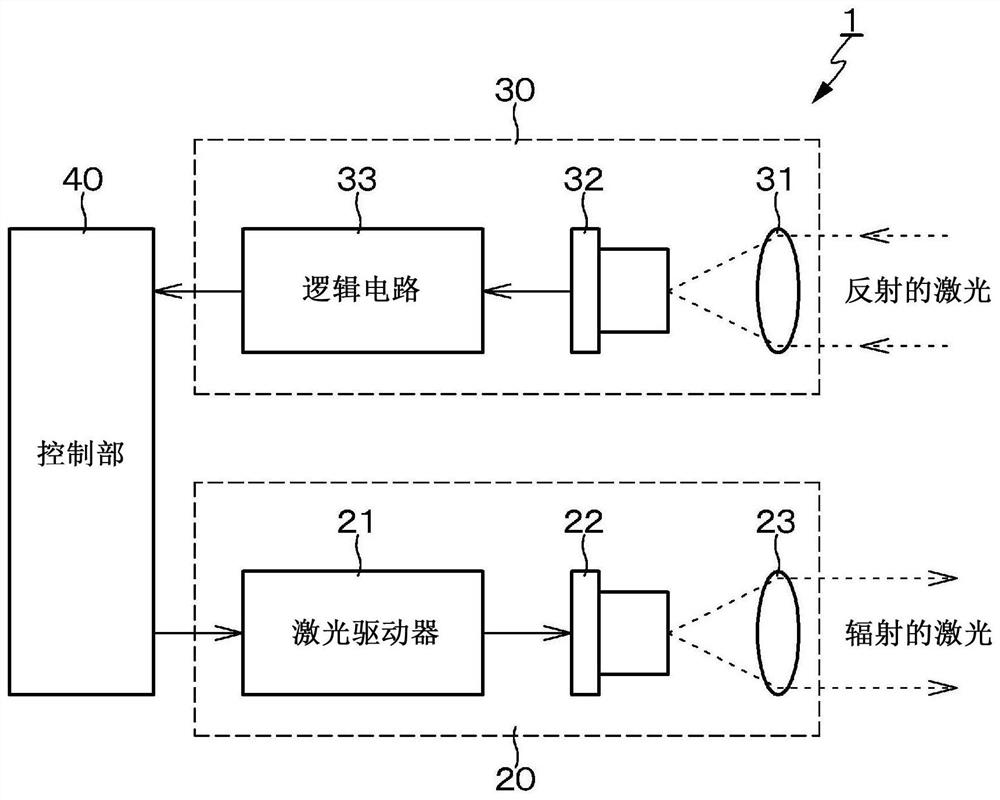
[0113] Example 3 is a modified example of Example 1, and in Example 3, correction processing is also performed for a delay common to all histograms. Here, examples of "a delay common to all histograms" include processing delays in circuits, delays outside the light receiving device 30, specifically, delays in wiring through which transmission Figure 2A The laser light source 22 of the light source 20 shown is a trigger signal for emitting light.
[0114] In Example 1, different delay corrections are performed for each histogram. However, in addition to the in-plane latency, there is the aforementioned latency common to all histograms. The presence of a delay common to all histograms results in an error between the distance measured by the light receiving device 30 and the actual distance, which error corresponds to the delay common to all histograms.
[0115] Therefore, in Example 3, different delay corrections are performed for each histogram, and also by using a system co...
PUM
 Abstract
Description
Claims
Application Information
 - R&D
- Intellectual Property
- Life Sciences
- Materials
- Tech Scout
- Unparalleled Data Quality
- Higher Quality Content
- 60% Fewer Hallucinations
Browse by: Latest US Patents, China's latest patents, Technical Efficacy Thesaurus, Application Domain, Technology Topic, Popular Technical Reports.
© 2025 PatSnap. All rights reserved.Legal|Privacy policy|Modern Slavery Act Transparency Statement|Sitemap|About US| Contact US: help@patsnap.com