Lower limb artificial limb knee joint capable of combining active type and passive type

A knee joint, active and passive technology, applied in prosthetics, medical science, artificial legs, etc., can solve the problems of restricting the activities of prosthetic users, heavy weight and large size of mainstream prosthetics, and achieve smooth walking, comfortable use, and good The effect of damping properties

Pending Publication Date: 2021-03-19
国家康复辅具研究中心
View PDF0 Cites 2 Cited by
  • Summary
  • Abstract
  • Description
  • Claims
  • Application Information

AI Technical Summary

Problems solved by technology

[0003] The current mainstream prosthetics in the market are usually non-powered, and their flexion and extension movements are driven by the thigh stump. Due to the different conditions of the wearer, it may be difficult to walk or go upstairs
The bending degree of the mainstream prosthetic knee joint is about 0-120°, which limits the activities of the prosthetic user
Current mainstream prosthetics are heavy and large in size

Method used


Image

  • Lower limb artificial limb knee joint capable of combining active type and passive type
  • Lower limb artificial limb knee joint capable of combining active type and passive type
  • Lower limb artificial limb knee joint capable of combining active type and passive type

Examples


specific Embodiment approach 1

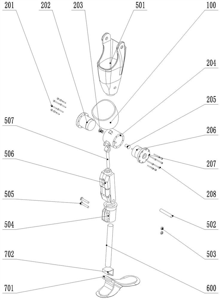
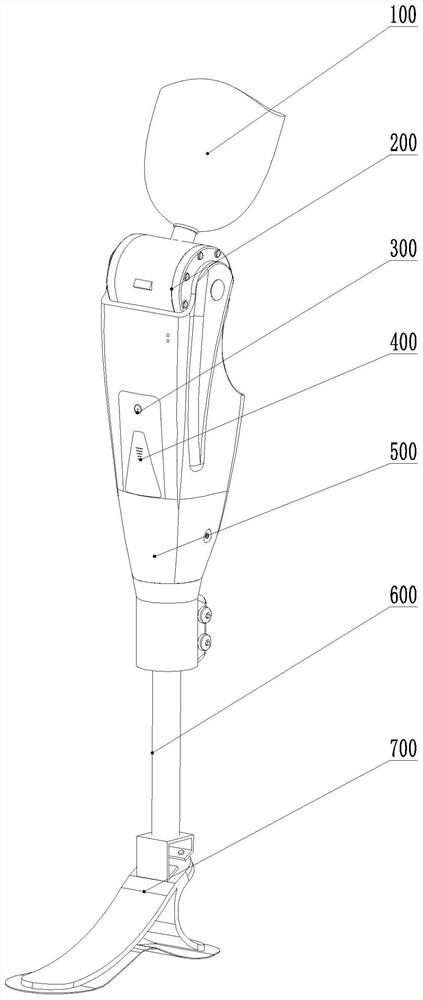
[0023] Specific implementation mode one: as figure 2 , Figure 4-Figure 7 As shown, this embodiment discloses an active-passive combined lower limb prosthetic knee joint, including a receiving cavity 100, a rotating joint shaft 200, a control panel 300, a Bluetooth communication module 400, a dynamic knee joint 500, a calf rod 600 and carbon fiber Energy storage feet 700;

[0024] The lower end of the receiving cavity 100 is fixedly connected with the upper end of the rotating joint shaft 200, and the rotating joint shaft 200 is fixedly connected with the dynamic knee joint 500. The lower end of the joint 500 is fixedly connected, and the lower end of the calf rod 600 is fixedly connected with the upper end of the carbon fiber energy storage foot 700. A control panel 300 and a Bluetooth communication module 400 are fixed on the outer wall of the dynamic knee joint 500. The control panel 300 is used to control the rotation of the joint The motor 206 of the shaft 200 is start...

specific Embodiment approach 2

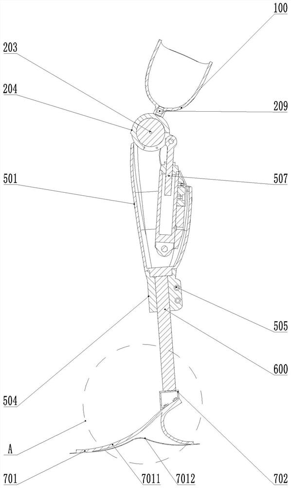
[0025] Specific implementation mode two: as Figure 1-Figure 6 As shown, this embodiment is a further description of Embodiment 1. The rotary joint shaft 200 includes a reducer 202, a spline shaft 203, a hollow joint shaft 204, a bearing end cover 205, a motor 206, a right end cover 207, Mechanical adapter 209 and angle sensor 210;

[0026] The hollow joint shaft 204 is arranged horizontally, and the upper end of the outer wall of the hollow joint shaft 204 is fixedly connected to the lower end of the receiving cavity 100 through a mechanical adapter 209. The left end inside, the motor 206 and the right end cover 207 (using the right end cover fixing screw 208) are axially fixed on the right end of the hollow joint shaft 204, the angle sensor 210 is fixed on the right side of the motor 206, and the output shaft of the motor 206 It is connected with the input shaft of the reducer 202, and the outer end surface of the output shaft of the reducer 202 is provided with a spline ho...

specific Embodiment approach 3

[0027] Specific implementation mode three: as Figure 1-Figure 6 As shown, this embodiment is a further description of Embodiment 1. The dynamic knee joint 500 includes a calf housing 501, a long shaft 502, a calf connection sleeve 504, a damping cylinder 506, and a guide rod 507;

[0028] The upper end of the guide rod 507 is rotatably connected to the outer wall of the hollow joint shaft 204, and the lower end of the guide rod 507 is connected to the upper end of the piston rod of the damping cylinder 506. The long axis 502 is connected to the lower side wall of the lower leg housing 501;

[0029] The shank connecting sleeve 504 is two symmetrical split structures, the upper end of the shank connecting sleeve 504 is slidably connected with the lower end of the shank shell 501 (the lower end of the shank shell 501 is provided with two slideways in parallel, the upper end of the shank connecting sleeve 504 is connected to the two The upper end of the calf rod 600 is set in th...


PUM


Abstract

The invention discloses a lower limb artificial limb knee joint capable of combining an active type and a passive type, and belongs to the technical field of rehabilitation auxiliary tools. The lowerlimb artificial limb knee joint comprises a socket body, a rotary joint axis, a control panel, a Bluetooth communication module, a power knee joint, a shank rod and a carbon fiber energy storage foot,wherein the lower end of the socket body is fixedly connected with the upper end of the rotary joint axis; the rotary joint axis is fixedly connected with the power knee joint; the rotary joint axisdrives the power knee joint to rotate; the upper end of the shank rod is fixedly connected with the lower end of the power knee joint; the lower end of the shank rod is fixedly connected with the upper end of the carbon fiber energy storage foot; the outer wall of the power knee joint is fixedly provided with the control panel and the Bluetooth communication module; the control panel is used for controlling startup and shutdown of the motor of the rotary joint axis; and the driver of the control panel drives the motor to regulate a revolving speed and a rotation angle. The lower limb artificial limb knee joint adopts a way of combining the active type and the passive type, motor driving is added into the hollow joint axis, the problem that a passive damping type artificial limb can not provide an active moment is solved, and meanwhile, a damping oil cylinder is used for guaranteeing good damping performance under a situation that the active moment is not required.

Description

technical field [0001] The invention belongs to the technical field of rehabilitation aids, and in particular relates to an active-passive combined lower limb prosthetic knee joint. Background technique [0002] The installation and popularization of lower limb prosthesis is an important means to solve the basic needs of amputees. The installation of artificial limbs can not only restore the original shape and function of the patient's disabled limbs, but also avoid the adverse effects of amputation on the patient. Existing prosthetic products can be divided into active prostheses, passive prostheses and semi-active prostheses according to their control methods. Active prostheses are mainly controlled by electric motors, hydraulic pressure, and air pressure, which are large in size and high in energy consumption. Passive prosthetics are controlled by residual limbs, with fixed pace, poor coordination, and high damping requirements. Semi-active prosthetics are controlled b...

Claims


Application Information

Patent Timeline
Patent Type & Authority Applications(China)
IPC IPC(8): A61F2/60A61F2/64A61F2/70
CPCA61F2/60A61F2/64A61F2002/701
Inventor 张秀峰张宁徐建光
Owner 国家康复辅具研究中心
Why Eureka
Try Eureka