a pressure tank

A pressure tank and tank body technology, applied in the field of pressure tanks, can solve problems such as air reduction, and achieve the effect of preventing insufficient air or excessive inflation

Active Publication Date: 2022-07-19
广东省佰荣压力容器有限公司
View PDF5 Cites 0 Cited by
  • Summary
  • Abstract
  • Description
  • Claims
  • Application Information

AI Technical Summary

Problems solved by technology

[0004] In order to solve the problem that the air in the pressure tank is reduced due to dissolving in water, the present invention proposes a pressure tank that does not take up space and can automatically replenish air

Method used


Image

  • a pressure tank
  • a pressure tank
  • a pressure tank

Examples


Embodiment Construction

[0017] The present invention will be further described below with reference to the accompanying drawings and specific embodiments.

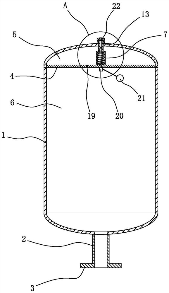
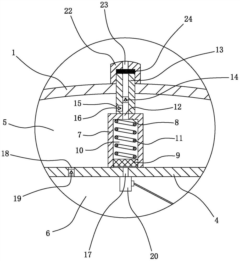
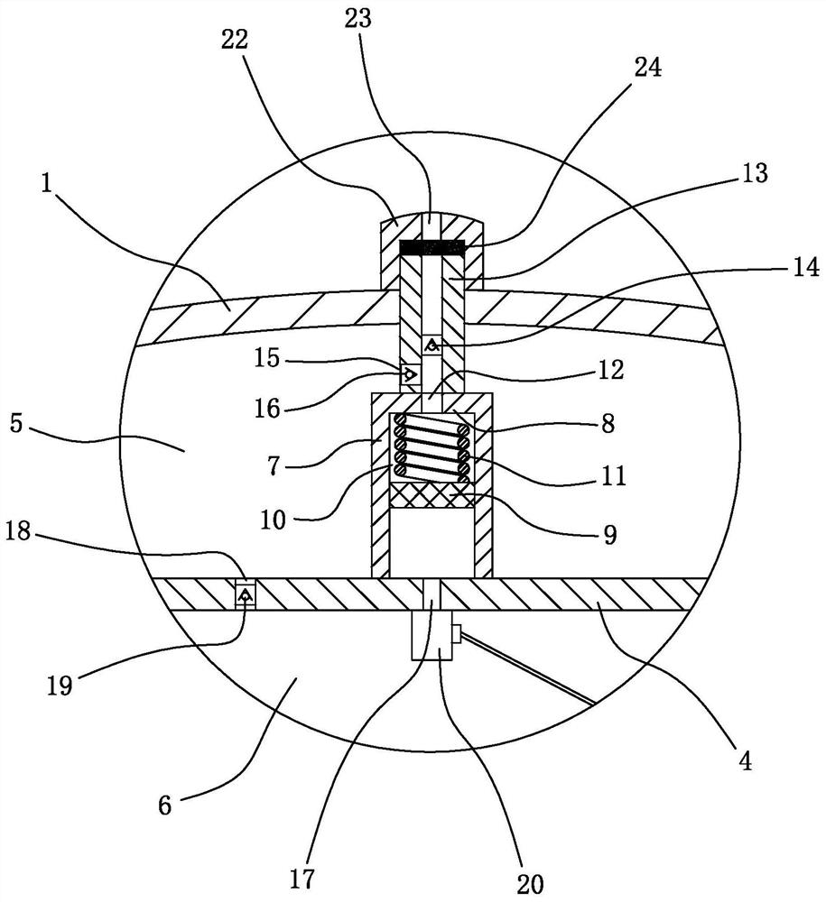
[0018] see Figure 1 to Figure 3 , a pressure tank, including a tank body 1, the bottom of the tank body 1 is provided with a connecting pipe 2, one end of the connecting pipe 2 is connected with the tank body 1, and the other end is provided with a connecting flange 3, the tank body 1 is horizontally arranged There is a partition 4 , the partition 4 divides the tank body 1 into a pressure storage chamber 5 and a water storage chamber 6 , and the pressure storage chamber 5 is located on the upper side of the water storage chamber 6 .

[0019] The pressure storage chamber 5 is provided with a booster pipe 7, the lower end of the booster pipe 7 is sealed and fixed with the upper surface of the partition plate 4, the upper end of the booster pipe 7 is provided with a sealing plate 8, and the pipe of the booster pipe 7 is sealed. There is a piston 9...


PUM


Abstract

The invention discloses a pressure tank, which relates to the technical field of secondary water supply equipment. The baffle plate divides the tank into a pressure storage cavity and a water storage cavity. There is a booster pipe in the pressure storage cavity. The upper end of the booster pipe is provided with a sealing plate. The piston is located between the piston and the sealing plate to form a pressurized chamber in the pressurized pipe hole, a return spring is arranged in the pressurized chamber, a ventilation hole is provided on the sealing plate, and a ventilation pipe is fixed on the upper side of the sealing plate. A first one-way valve is arranged in the pipe hole of the trachea, an air outlet is provided on the pipe wall of the air pipe, a second one-way valve is arranged in the air outlet, a balance hole and an air supply hole are arranged on the clapboard, and the air supply hole is provided with a second one-way valve. There is a third check valve. In order to solve the problem that the air in the pressure tank is reduced by dissolving in water, the present invention proposes a pressure tank that does not occupy space and can automatically supplement air.

Description

technical field [0001] The invention relates to the technical field of secondary water supply equipment, in particular to a pressure tank. Background technique [0002] The pressure tank is often used in secondary water supply equipment. Its working principle is to fill a certain amount of air in the pressure tank in advance. When the water pressure increases, the compressed air is used to absorb the impact of water hammer. [0003] However, the air in the pressure tank is in direct contact with water, and the air will be reduced by dissolving in the water, so that the effect of balancing the water volume and pressure will be weakened or lost. SUMMARY OF THE INVENTION [0004] In order to solve the problem that the air in the pressure tank is reduced by dissolving in water, the present invention proposes a pressure tank that does not occupy space and can automatically supplement air. [0005] In order to achieve the above purpose, the present invention adopts the followin...

Claims


Application Information

Patent Timeline
Patent Type & Authority Patents(China)
IPC IPC(8): E03B11/06E03B11/08E03B7/07
CPCE03B11/06E03B11/08E03B7/075Y02A20/00
Inventor 徐辉
Owner 广东省佰荣压力容器有限公司
Why Eureka
Try Eureka