Ventilation skylight structure of a green building and using method thereof

A technology for ventilating skylights and green buildings. It is applied in the direction of building structures, buildings, skylights/dome, etc. It can solve the problems of window frame removal, small opening area, and ventilation, so as to avoid potential safety hazards, adjust the ventilation area, The effect of large ventilation area

Inactive Publication Date: 2022-05-06
深圳市成豪建设集团有限公司
View PDF0 Cites 0 Cited by
  • Summary
  • Abstract
  • Description
  • Claims
  • Application Information

AI Technical Summary

Problems solved by technology

[0004] Among them, while the pull-and-translate skylight cannot be fully opened, the two movable window bodies cannot be removed from the window frame when in use, and the opening area is narrow, and the entire window frame cannot be unfolded for ventilation; at the same time, the When this kind of skylight is used vertically or inclined, there is no real-time limit to the use position of the movable window body, so that the skylight structure only has a fully open and closed state, and cannot be used for ventilation in rainy weather;
[0005] Among them, the push-opening sunroof needs a large thrust to overcome gravity during use, and the opening angle is small. At the same time, it is easy to be blown over by strong winds in windy weather after being opened, forming a safety hazard; , the side facing the wind is easy to block the movement of leaves and other objects that can move with the wind, and the blocked objects are easy to fall into the building through the skylight; The skylight is blocked, and the ventilation effect at this time is not good; at the same time, the skylight cannot be used for ventilation in rainy weather

Method used


Image

  • Ventilation skylight structure of a green building and using method thereof
  • Ventilation skylight structure of a green building and using method thereof
  • Ventilation skylight structure of a green building and using method thereof

Examples


Embodiment Construction

[0055] The following will clearly and completely describe the technical solutions in the embodiments of the present invention with reference to the accompanying drawings in the embodiments of the present invention. Obviously, the described embodiments are only some, not all, embodiments of the present invention. Based on the embodiments of the present invention, all other embodiments obtained by persons of ordinary skill in the art without creative efforts fall within the protection scope of the present invention.

[0056] In describing the present invention, it is to be understood that the terms "opening", "upper", "lower", "thickness", "top", "middle", "length", "inner", "surrounding" etc. Indicating orientation or positional relationship is only for the convenience of describing the present invention and simplifying the description, and does not indicate or imply that the components or elements referred to must have a specific orientation, be constructed and operated in a sp...


PUM


Abstract

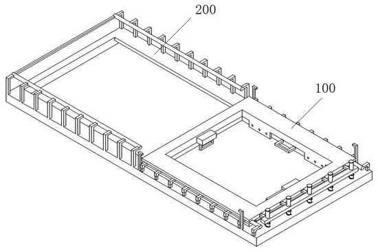
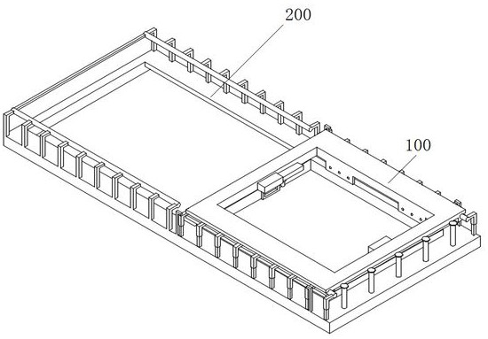
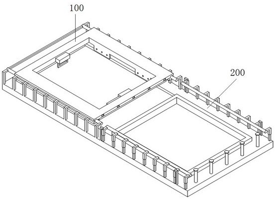
The invention discloses a ventilation skylight structure of a green building and an installation method thereof, and relates to the technical field of building skylight devices. The skylight structure of the present invention includes a skylight mounting frame and a skylight body; the skylight body includes a rectangular outer frame, a rectangular outer frame, and a ring-shaped boss arranged on the inner side, and side rails are arranged on both sides of the rectangular outer frame. a slot; the skylight mounting frame includes a rectangular outer frame 2, a cross beam is arranged in the rectangular outer frame 2, and a rectangular outer frame 2 located on one side of the transverse beam is provided with a ring-shaped convex edge matched with the annular groove; the rectangular outer frame Both sides of the second are provided with a number of support structures 1 and 2. The support structure 1 and the support structure 2 are respectively provided with a sliding component 1 and a sliding component 2 which are matched with the notch. The sunroof structure of the present invention is set by the cooperation of the sunroof mounting frame and the sunroof body, and has three use states of open, closed and half-open, and can be used according to actual needs.

Description

technical field [0001] The invention belongs to the technical field of building skylight devices, and in particular relates to a ventilation skylight structure of a green building and a use method thereof. Background technique [0002] With the continuous development of the construction industry and people's pursuit of a higher quality of life, skylights have been widely used as lighting and ventilation devices for buildings. [0003] Common existing skylight structures include push-open skylights and pull-out translation skylights; [0004] Among them, while the pull-and-translate skylight cannot be fully opened, the two movable window bodies cannot be removed from the window frame when in use, and the opening area is narrow, and the entire window frame cannot be unfolded for ventilation; at the same time, the When this kind of skylight is used vertically or inclined, there is no real-time limit to the use position of the movable window body, so that the skylight structure...

Claims


Application Information

Patent Timeline
Patent Type & Authority Patents(China)
IPC IPC(8): E04D13/03E04D13/035
CPCE04D13/03E04D13/0325E04D13/0351
Inventor 陈丽
Owner 深圳市成豪建设集团有限公司
Why Eureka
Try Eureka