Surgical system

A surgical operation and tracking system technology, applied in the field of end effectors, can solve the problems of entering patients, saw blades limiting cutting accuracy, etc.

Pending Publication Date: 2021-03-30
GLOBUS MEDICAL INC
0 Cites 3 Cited by

AI-Extracted Technical Summary

Problems solved by technology

Errors in fixture placement and limited stability of the saw blade during cutting can limit the accuracy of t...

Method used

[0053] As with the robot base 10, a plurality of driven wheels 12 may be attached to the camera base 38. Similar to the operation of the robotic base 10 and driven wheels 12 , the driven wheels 12 may allow the camera tracking system 6 to be stabilized and leveled or set in a fixed orientation relative to the patient 50 . This stabilization can prevent camera tracking system 6 from moving during a medical procedure, and can prevent camera 46 from losing sight of one or more DRAs 52 attached to anatomical structures 54 and/or tools 58 within a designated area 56 as shown in FIG. 5 . track. This stability and maintenance of tracking enhances the ability of the surgical robot 4 to operate effectively with the camera tracking system 6 . Additionally, wide camera mount 38 may provide additional support for camera tracking system 6 . Specifically, as illustrated in FIG. 5 , the wide camera mount 38 prevents the camera tracking system 6 from tipping when the camera 46 is positioned on the patient. Without a wide camera mount 38, the protruding camera 46 could unbalance the camera tracking system 6, which could cause the camera tracking system 6 to tip over.
[0096] As will be explained in further detail below, the various passive end effectors illustrated in FIGS. 12-19 each comprise a base, a first planar mechanism, and a second planar mechanism. The base is configured to attach to an end effector coupling (eg, end effector coupling 22 in FIGS. 4 and 5 ) of a robotic arm (eg, robotic arm 18 in FIGS. 1 and 2 ) positioned by a surgical robot. . Various clamping mechanisms can be used to securely attach the base to the end effector c...

Abstract

A passive end effector of a surgical system includes a base, a first mechanism, and a second mechanism. The base attaches to an end effector coupler of a robot arm positioned by a surgical robot. Thefirst mechanism extends between a rotatable connection to the base and a rotatable connection to a tool attachment mechanism. The second mechanism extends between a rotatable connection to the base and a rotatable connection to the tool attachment mechanism. The first and second mechanisms pivot about the rotatable connections to constrain movement of the tool attachment mechanism to a range of movement within a working plane. The tool attachment mechanism is configured to connect to a surgical saw including a saw blade for cutting.

Application Domain

DiagnosticsComputer-aided planning/modelling +5

Technology Topic

EngineeringArm position +5

Image

  • Surgical system
  • Surgical system
  • Surgical system

Examples

  • Experimental program(1)

Example Embodiment

[0030] Referring now to the accompanying drawings, embodiments of the invention are described below, and examples of embodiments of the invention are shown in the drawings. The invention can be implemented in many different forms and should not be construed as being limited to the embodiments listed herein. Instead, these embodiments are provided such that the present disclosure is more complete and complete, and the scope of the concepts of each of the invention is completely transversely conveyed to those skilled in the art. It should also be noted that these embodiments are not mutually exclusive. The components in one embodiment can be illustrated or for another embodiment by default.
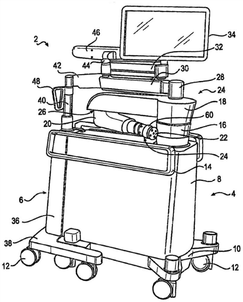
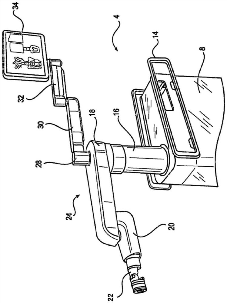
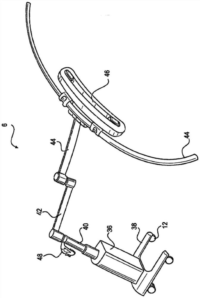
[0031] Various embodiments disclosed herein relate to improvements in the operation of the surgical system during interoperative surgical intervention in which the surgery is performed. A passive end effector that can be connected to a robotic arm positioned by a surgical robot is disclosed. The passive end effector has a mechanism that limits the movement of the tool attachment mechanism within a certain mobile range. The tool attached to the surgical saw for cutting, such as a sagittal saw with a swing type saw blade. The mechanism can be configured to limit the cutting plane of the saw blade to a working plane. The surgical robot can determine the gesture of the target plane based on a surgical plan of the cut position and based on the anatomical structure of the anatomical structure, and may be based on the attitude and the place to the target plane. The comparison of the posture of the surgical saw is generated for manipulation information. The manipulation information indicates where the passive end effector needs to move, so that the cutting plane of the saw blade becomes equal to the target flat, and the saw blade is positioned in the anatomy of the desired. The structure is within a distance, the distance within the movement range of the tool attachment mechanism of the passive end effector.
[0032] These and other related embodiments can be operable to improve the accuracy of the saw blade guidance than other robots and manual (e.g., fixtures) solutions for surgery. The mechanism of the passive end effector allows the surgeon to concentrate on intensive interpretation of direct force feedback when using surgical saw cutting bones guided by passive end effectors. The mechanism may be a planar mechanism, for example, having a tip joint having one degree of freedom, the terminal joint being configured to limit the cutting plane to the target flat. The surgeon can also detect and control the speed of bone removal based on audio and / or visual notification feedback provided by surgical robots.
[0033] These embodiments can be in art surgery with high precision, high rigidity, sufficient workspace and direct feedback, and in particular during knee surgery. As will be explained in detail below, the tracking system can be used to accurately align the cutting plane with the target plane to cut the bone. When the surgeon moves the saw blade along the cut plane and directly senses the force feedback of the saw blade cutting the skeleton, high-precision cut can be achieved by limiting the plane mechanism of the target plane to the target plane. In addition, these examples can be quickly adopted to surgical practices by defined changes in the conventionally recognized surgical workflow.
[0034] figure 1 Examples of the surgical system 2 according to some embodiments disclosed are shown. Using, for example, before performing orthopedic surgery Figure 10 C-arm imaging device 104 or Figure 11 O-arm imaging apparatus 106, or another medical imaging device such as a computer tomography (CT) image or MRI, three-dimensional ("3D") image scanning is performed on the patient's plan surgery area. This scan can be carried out before surgery (such as a few weeks, most common) or in surgery. However, any known 3D or 2D image scan can be used in accordance with various embodiments of the surgical system 2. Send image scan to a computer platform that communicates with the surgical system 2, such as Figure 9 Surgery system computer platform 900, which includes surgical robot 800 (for example, figure 1 The robot 2) and the surgical plan computer 910. Surgeon View Surgery Plan Computer 910 ( Figure 9 One or more image scans on the display device generates a surgical plan defining a target plane, and cuts the patient's anatomical structure in the target plane. This plane is a function of patient anatomical structure, selected implant and its size. In some embodiments, the surgical plan of the defined target plane is planned on a 3D image scan displayed on the display device.
[0035] figure 1 Surgical system 2 can help surgeons during medical procedures, such as holding tools, alignment tools, use tools, boot tools, and / or positioning tools to use to help surgeons. In some embodiments, the surgical system 2 includes a surgical robot 4 and a camera tracking system 6. Two systems can be mechanically coupled together by any different mechanisms. Suitable mechanisms may include, but are not limited to, mechanical latches, tether, clamps or supports, or magnetic surfaces or magnetized surfaces. The ability of the surgery robot 4 and the camera tracking system 6 can allow the surgical system 2 to manipulate and move as a single unit, and allow the surgical system 2 to have a small occupied space in the region, allowing easier to pass narrow The channel and the movement of the turn are moved and allowed to be stored within a smaller area.
[0036] Orthopedic surgery can begin to move from the medical storage room to the surgery system 2. Surgical system 2 can be operated through the doorway, the hall and elevator to reach the medical compartment. In the medical compartment, the surgical system 2 can be physically divided into two separate and different systems (surgical robots 4, and camera tracking system 6). Surgical robots 4 can be positioned adjacent to patients in any suitable location to suitably help medical staff. The camera tracking system 6 can be positioned at the bottom of the patient, in the patient's shoulder or any other position of the current attitude and posture movement of the trajectory portion of the surgical robot 4 and the patient. Surgical robots 4 and camera tracking system 6 can be powered and / or inserted into the outer wall outlet by airborne power supply and / or inserted into the outer wall outlet.
[0037] Surgery robots 4 can be used to help surgeons by maintaining and / or using tools during medical procedures. In order to properly utilize and maintain tools, surgery robots 4 can rely on multiple motors, computers, and / or actuators to properly work. Such as figure 1 The robot main 8 can be used to act as a plurality of motors, computers, and / or actuators can be fixed in the surgical robot 4. The robot main 8 can also provide support for the robot telescopic support arm 16. In some embodiments, the robot body 8 can be made of any suitable material. Suitable materials may be, but not limited to, metals such as titanium, aluminum or stainless steel, carbon fibers, fiberglass or heavy plastics. The size of the robot main 8 can provide a stable platform for supporting the attachment assembly, and can accommodate, hide and protect multiple motors, computers, and / or actuators that can operate attachment assemblies.
[0038] The robot base 10 can act as the lower support of the surgical robot 4. In some embodiments, the robot base 10 can support the robot main body 8 and can attach the robot main body 8 to a plurality of driven wheels 12. This attachment to the wheel can allow the robot main body 8 to be effectively moved in space. The robot base 10 can operate along the length and width of the robot main body 8. The robot base 10 can be from about two inches to about 10 inches. The robot base 10 can be made of any suitable material. Suitable materials may be, but not limited to, metal, carbon fibers, fiberglass or heavy plastics or resins such as titanium, aluminum or stainless steel. The robot base 10 can cover, protect and support the driven wheel 12.
[0039] In some embodiments, if figure 1 The at least one driven wheel 12 is shown can be attached to the robot base 10. The driven wheel 12 can be attached to the robot base 10 at any position. Each individual driven wheel 12 can rotate the vertical axis in any direction. The motor can be placed above or adjacent to its placement within the driven wheel 12. The motor allows the surgical system 2 to operate to any location and stabilize and / or leveling the surgical system 2. It can be pressed into the surface within the driven wheel 12 or adjacent to the rod. The poles not shown can be made of any suitable metal to enhance the surgical system 2. Suitable metals can be, but not limited to, stainless steel, aluminum or titanium. Additionally, the rod can include a buffer (not shown) on the side end of the contact surface, which prevents the rod from slipping and / or producing a suitable contact surface. The material can be any suitable material that acts as a buffer. Suitable materials may be, but not limited to, plastics, neoprene, rubber or textured metals. The rod can increase the driven wheel 10, which can increase the surgical system 2 to level or otherwise fix any height needed with respect to the direction of the patient's orientation. The weight of the surgical system 2 is supported by the small contact area of ​​the rod on each wheel to prevent the surgical system 2 from moving during the medical procedure. This rigid positioning prevents objects and / or people from accidentally moving surgical systems 2.
[0040] Mobile Surgery System 2 can be promoted using robotic track 14. The robot track 14 provides the ability to move the surgical system 2 in the case where the robot main body 8 is not grasped. Such as figure 1 The length of the robot track 14 can be as long as the robot main body 8, shorter than the robot body 8, and / or longer than the robot main body 8. The robot track 14 can be made of any suitable material. Suitable materials may be, but not limited to, metals such as titanium, aluminum or stainless steel, carbon fibers, fiberglass or heavy plastics. The robot track 14 can be further supplied to the robot main body 8, thereby preventing objects and / or medical personnel from contacting, hitting or hitting the robot body 8.
[0041] The robot main 8 can be supported for selecting a compliant articulated robot arm, referred to as "scara" below. Due to the repeatability and compactness of the robot, it is possible to use SCARA 24 within the surgical system 2. The compactness of Scar can provide additional space in the medical program, which allows medical professionals to perform medical procedures without excessive messy and restricted areas. SCARA 24 can include a robot telescoping support 16, a robot support arm 18, and / or a robot arm 20. The robot telescoping support 16 can be placed along the robot main body 8. Such as figure 1 The robot telescopic support 16 can be provided for SCARA 24 and display 34. In some embodiments, the robot telescoping support 16 can extend and shrink in the vertical direction. The robot telescoping support 16 can be made of any suitable material. Suitable materials may be, but not limited to, metals such as titanium or stainless steel, carbon fibers, fiberglass or heavy plastics. The body of the robot telescoping support 16 can be any width and / or height to support stress and weight placed thereon.
[0042] In some embodiments, the medical staff can move SCARA24 by a command submitted by the medical staff. The command can be derived from the input received on the display 34 and / or tablet. The command can come from the pressing of the switch and / or the pressing of multiple switches. Such as Figure 4 with 5 The activation assembly 60 can include switches and / or multiple switches. The activation assembly 60 can be operable to transmit a moving command to SCARA 24, thereby allowing the operator manually manually manually manually manually. When pressed the switch or multiple switches, the medical staff has the ability to easily move SCARA 24. Additionally, when SCARA 24 does not receive a moving command, SCARA 24 can be locked in an appropriate location to prevent accidental movement of medical personnel and / or other objects. By locking in the appropriate position, SCARA 24 provides a stable platform, on the stable platform, such as Figure 4 with 4 The passive end effector 1100 and the connected surgical saw 1140 are prepared for medical operation.
[0043] The robot support arm 18 can be placed on the robot telescopic support 16 by various mechanisms. In some embodiments, preferred see figure 1 with 2 The robot support arm 18 rotates in any direction with respect to the robot telescoping support 16. The robot support arm 18 can rotate three hundred and sixty degrees around the robot telescoping support 16. The robotic arm 20 can be connected to the robot support arm 18 at any suitable location. The robotic arm 20 can be attached to the robot support arm 16 through various mechanisms. Suitable mechanisms may be, but are not limited to, nuts and bolts, ball connectors, pressure fit, weldors, binders, screws, rivets, clamps, latchings, and / or any combination thereof. The robot arm 20 can rotate in any direction relative to the robot support arm 18, in the embodiment, the robot arm 20 can rotate three hundred and sixty degrees relative to the robot support arm 18. This free rotation allows the operator to position the robot arm 20 as planned.
[0044] Figure 4 with 5 The passive end effector 1100 can be attached to the robot arm 20 at any suitable location. As will be explained in further detail below, the passive end effector 1100 includes a base, a first mechanism, and a second mechanism. The base is configured to attach to the end effector coupling 22 of the robot arm 20 positioned by the surgical robot 4. Various mechanisms can include, but are not limited to, latching, jigs, nuts, bolts, spherical fittings, pressure engagement, weldors, binders, screws, rivets, and any combination thereof, the base can be attached by the various mechanisms. The end effector coupling 22 is connected. The first mechanism extends between the rotatable connector of the base and the rotatable connector to the tool attachment mechanism. The second mechanism extends between the rotatable connector to the base and the rotatable connector of the tool attachment mechanism. The first mechanism and the second mechanism are pivoted around the rotatable connector and can be configured to limit the movement of the tool attachment mechanism within the operating range within the working plane. The rotatable connector can be a pivot joint that allows 1 degree of freedom (DOF) to allow 2 DOF-moving universal joints, or 3 DOF spherical joints. The tool attachment mechanism is configured to connect to a surgical saw 1140 having a saw blade. Surgery saw 1140 can be configured to swing the saw blade for cutting. The first mechanism and the second mechanism can be configured to limit the cutting plane of the saw blade to parallel to the working plane. When the passive end effector is configured to limit the motion of the saw blade to the cutting plane, the pivot joint can preferably be used to connect the plane mechanism.
[0045] The tool attachment mechanism can be connected to the surgical saw 1140 through a variety of mechanisms, which may include, but are not limited to, screws, nuts, bolts, jigs, latch, tether, pressure fit or magnets. In some embodiments, the dynamic reference array 52 is attached to the passive end effector 1100, such as attached to the tool attachment mechanism, and / or attached to the surgical saw 1140. Dynamic reference arrays (also known as "DRA" herein) are rigid bodies that can be placed in patients, surgical robots, passive end effectors, and / or surgical saws during navigation surgery procedures. The camera tracking system 6 or other 3D positioning system is configured to track the posture of the Track mark of DRA (eg, position and rotation). The tracking tag contains a baseline, such as the presented placement of the ball. This tracking of 3D coordinates for tracking tags can allow surgical system 2 to determine that DRA52 is relative to Figure 5 The gesture in any space of the target anatomy of the patient 50.
[0046] Such as figure 1 The light indicator 28 can be positioned at the top of SCARA 24. The light indicator 28 can illuminate as any type of light to indicate "condition" in which the surgical system 2 is currently operated. For example, green lighting can indicate that all systems are normal. Illuminating red can indicate that the surgical system 2 is not operating normally. Pulsating lights can mean that the surgical system 2 is performing functionality. The combination of lights and pulsations can produce almost unlimited quantities, communicate current operating conditions, status, or other operational instructions in the combination. In some embodiments, the light can be generated by an LED bulb which can form a ring around the light indicator 28. The light indicator 28 can include a fully permeable material that allows the light to pass through the lighting indicator 28.
[0047] The light indicator 28 can be attached to the lower display support 30. Such as figure 2 The lower display support 30 may allow the operator to manipulate the display 34 to any suitable location. The lower display support 30 can be attached to the lighting indicator 28 by any suitable mechanism. In an embodiment, the lower display support 30 can be rotated around the light indicator 28. In an embodiment, the lower display support 30 can rigidly attach to the light indicator 28. Then, the light indicator 28 can rotate three hundred and sixty degrees around the robot support arm 18. The lower display support 30 can be any suitable length, and the suitable length can be about eight inters into about 34 inches. The lower display support 30 can act as a base of the upper display support 32.
[0048] The upper display support 32 can be attached to the lower display support 30 by any suitable mechanism. The upper display support 32 can be any suitable length, and the suitable length can be about eight inters into about 34 inches. In an embodiment, if figure 1 The upper display support 32 can be displayed in the upper display support 32 to rotate three hundred and sixty degrees with respect to the upper display support 32. Also, the upper display support 32 can rotate three hundred and sixty degrees relative to the lower display support 30.
[0049] Display 34 can be any device supported by the upper display support 32. In an embodiment, if figure 2 The display 34 can be displayed can produce a color and / or black and white image. The width of the display 34 can be about eight inters into about 30 inches wide. The height of the display 34 can be from about six inches to about twenty-two inches. The depth of the display 34 can be about half inch to about four inches.
[0050] In an embodiment, the tablet can be bonded to the display 34 and / or is not used in conjunction with the display 34. In an embodiment, the table can be placed on the upper display support 32 instead of the display 34, and can be removed from the upper display support 32 during the medical operation. Additionally, the tablet can communicate with the display 34. The tablet can be connected to the surgical robot 4 through any suitable wireless and / or wired connection. In some embodiments, the tablet can program and / or control the surgical system 2 during medical operation. When the surgical system 2 is controlled with a tablet, all input and output commands can be copied on the display 34. Using a tablet allows the operator to manipulate surgical robots 4 without having to move around patients 50 and / or surgical robots 4.
[0051] Such as Figure 5 The camera tracking system 6 works with the surgical robot 4 through a wired or wireless communication network. reference figure 1 with 5 The camera tracking system 6 can contain some components similar to the surgical robot 4. For example, the camera main body 36 can provide the function found in the robot main body 8. The robot main 8 can provide a structure on which the camera 46 is mounted thereon. The structure in the robot main 8 can also provide support for the electronic device, communication device, and power supply for operating the camera tracking system 6. The camera main body 36 can be made of the same material as the robot body 8. The camera tracking system 6 can communicate directly to the tablet and / or display 34 via a wireless and / or wired network such that the tablet and / or display 34 can control the function of the camera tracking system 6.
[0052]The camera main body 36 is supported by the camera base 38. Camera base 38 can be used as a robot base 10. in figure 1 In the embodiment, the camera base 38 can be wider than the robot base 10. The width of the camera base 38 can allow the camera tracking system 6 to connect to the surgical robot 4. Such as figure 1 The width of the camera base 38 can be sufficiently large enough to suit the outer portion of the robot base 10. When the camera tracking system 6 is connected to the surgical robot 4, additional width of the camera base 38 can allow the surgical system 2 to provide additional operability and support for the surgical system 2.
[0053] As the robot base 10, the plurality of driven wheels 12 can be attached to the camera base 38. Similar to the operation of the robot base 10 and the driven wheel 12, the driven wheel 12 may allow the camera tracking system 6 to stabilize and level or set up to the patient 50. This stability prevents the camera tracking system 6 from moving during medical procedures, and prevents camera 46 from being lost. Figure 5 The displayed specified area 56 is connected to one or more DRA 52 of the anatomical structure 54 and / or the tool 58. This stability and maintenance of tracking enhances the ability of surgical robots 4 with the camera tracking system 6. Additionally, the width camera base 38 can provide additional support for the camera tracking system 6. Specifically, such as Figure 5 The width camera base 38 prevents the camera tracking system 6 when the camera 46 is placed on the patient. In the case where there is no wide camera base 38, the extended camera 46 may make the camera tracking system 6 imbalance, which may cause the camera tracking system 6 to fall.
[0054] The camera telescoping support 40 can support the camera 46. In an embodiment, the telescoping support 40 can move the camera 46 at higher or lower in the vertical direction. The telescopic support 40 can be made of any suitable material in which the camera 46 is supported. Suitable materials may be, but not limited to, metals such as titanium, aluminum or stainless steel, carbon fibers, fiberglass or heavy plastics. The camera handle 48 can be attached to the camera telescoping support 40 in any suitable position. The camera handle 48 can be any suitable handle configuration. Suitable configurations can be, but are not limited to, strip, circular, triangular, square, and / or any combination thereof. Such as figure 1 The camera handle 48 can be a triangle, thereby allowing the operator to move the camera tracking system 6 to the planned location prior to the medical operation. In an embodiment, the camera handle 48 can be used to reduce and raise the camera telescoping support 40. The camera handle 48 can perform an increase and decrease in the camera telescopic support 40 by pressing a button, a switch, a lever, and / or any combination thereof.
[0055] The lower camera support arm 42 can be attached to the camera telescoping support 40 in any suitable position, in the embodiment, such as figure 1 The lower camera support arm 42 can be rotated about three hundred and sixty degrees around the telescopic support 40. This free rotation allows the operator to position the camera 46 in any suitable location. The lower camera support arm 42 can be made of any suitable material in which the camera 46 is supported. Suitable materials may be, but not limited to, metals such as titanium, aluminum or stainless steel, carbon fibers, fiberglass or heavy plastics. The cross section of the lower camera support arm 42 can be any suitable shape. Suitable cross-sectional shapes may be, but not limited to, circular, square, rectangular, hexagonal, octagonal or workbeam. The length and width of the cross section can be about one to ten inches. The lower camera support arm can be from about four inches to about 36 inches. The lower camera support arm 42 can be coupled to the telescopic support 40 by any suitable mechanism. Suitable mechanisms may be, but are not limited to, nuts and bolts, ball connectors, pressure fit, weldors, binders, screws, rivets, clamps, latchings, and / or any combination thereof. The lower camera support arm 42 can be used to provide support for camera 46. The camera 46 can be attached to the lower camera support arm 42 by any suitable mechanism. Suitable mechanisms may be, but are not limited to, nuts and bolts, ball joints, pressure fit, weldors, binders, screws, rivets, and / or any combination thereof. The camera 46 can pivot in any direction between the camera 46 and the lower camera support arm 42. In an embodiment, the curved track 44 can be placed on the lower camera support arm 42.
[0056] The curved track 44 can be placed in any suitable location on the lower camera support arm 42. Such as image 3 The curved track 44 can be attached to the lower camera support arm 42 by any suitable mechanism. Suitable mechanisms may be, but are not limited to, nuts and bolts, ball connectors, pressure fit, weldors, binders, screws, rivets, clamps, latchings, and / or any combination thereof. The curved track 44 can be any suitable shape, and the suitable shape can be a new moon shape, a circular, a flat, an elliptical shape, and / or any combination thereof. In an embodiment, the curved track 44 can be any suitable length. An appropriate length can be approximately one foot to about six feet. The camera 46 can be movably placed along the bending track 44. The camera 46 can be attached to the curved track 44 by any suitable mechanism. Suitable mechanisms may be, but are not limited to, rolls, brackets, bars, motors, and / or any combination thereof. The unplanned motor and roller can be used to move the camera 46 along the bend rail 44. Such as image 3 The displayed, during the medical procedure, if the object prevents the camera 46 to observe one or more DRA 52, the motor can move the camera 46 along the curved rail 44. This movement movement can allow the camera 46 to move to a new location that is no longer hindering by the object without moving the camera tracking system 6. When it is hindered to the camera 46 to observe the DRA 52, the camera tracking system 6 can send a stop signal to the surgical robot 4, the display 34, and / or tablet. The stop signal can prevent SCARA 24 from moving until the camera 46 reaches DRA 52. This stop can prevent SCARA 24 and / or end effector coupling 22 to move and / or use medical tools without being tracked by the surgical system 2.
[0057] Such as Figure 6 The end effector coupling 22 is shown is configured to connect various types of passive end effectors to the surgical robot 4. The end effector coupling 22 can include a saddle joint 62, an activation assembly 60, a dynamic sensor 64 ( Figure 7 ) And connector 66. The saddle joint 62 can attach the end actuator coupling 22 to SCARA 24. The saddle joint 62 can be made of any suitable material. Suitable materials may be, but not limited to, metals such as titanium, aluminum or stainless steel, carbon fibers, fiberglass or heavy plastics. The saddle joint 62 can be made of a single metal, which can provide additional strength and durability for the end effector. The saddle joint 62 can be attached to SCARA 24 by attachment point 68. There may be a plurality of attach points 68 that surround the saddle joint 62. Attach points 68 can be sinking, embedded / or placed on the saddle joint 62. In some examples, screws, nuts, and bolts and / or any combinations thereof may pass through the attachment point 68 and secured the saddle joint 62 to SCARA 24. Nuts and bolts can connect the saddle joint 62 to the motor (not shown) within Scara 24. The motor can move the saddle joint 62 in any direction. The motor can further prevent the saddle joint 62 from being moved due to unexpected collisions and / or unexpected contacts by active servo or passive by application of a spring due to unexpected collisions and / or unexpected contacts.
[0058] The end effector coupling 22 can include a dynamic sensor 64 inserted between the saddle joint 62 and the connected passive end effector. Such as Figure 7 The dynamic sensor 64 can be attached to the saddle 62 by any suitable mechanism. Suitable mechanisms may be, but not limited to, screws, nuts, and bolts, threads, pressure fit, and / or any combination thereof.
[0059] Figure 8 A block diagram of the assembly of the surgical system 800 in accordance with some embodiments disclosed. reference Figure 7 with 8 The dynamic sensor 64 can be any suitable instrument for detecting and measurement. In some examples, the dynamic sensor 64 can be a six-axis dynamometer, a three-axis force sensor or a single-axis dynamometer. The dynamic sensor 64 can be used to track the force applied to the end effector coupling 22. In some embodiments, the dynamic sensor 64 can communicate with a plurality of motors 850, 851, 852, 853, and / or 854. When the force sensor 64 senses force, information about the amount of force on the applied force can be distributed from the switch array and / or the plurality of switch arrays to the controller 846. Controller 846 can acquire power information from the dynamic sensor 64, and process it with a switching algorithm. Controller 846 uses a switching algorithm to control motor driver 842. Motor driver 842 controls the operation of one or more motors. Motor driver 842 can guide a particular motor to generate, for example, the force measured by the dynamic sensor 64 by the motor measurement. In some embodiments, as indicated by controller 846, the resulting force can be from a plurality of motors, such as 850-854. Additionally, motor driver 842 can receive input from controller 846. The controller 846 can receive information from the dynamic sensor 64 to the direction of the force sensed by the dynamometer 64. Controller 846 can use motion controller algorithms to process this information. The algorithm can be used to provide information to a particular motor driver 842. For the direction of copying power, the controller 846 can activate and / or deactivate some motor drivers 842. Controller 846 can control one or more motors, such as one or more of 850-854 to induce movement of the passive end effector 1100 in the direction of the force sensed by the dynamometer 64. This force control can allow the operator to move SCARA 24 and the passive end effector 1100 in a very small resistance. The movement of the passive end effector 1100 can be performed to position the passive end effector 1100 in any suitable attitude (ie, the position and angle of the orthogonal reference axis with respect to the limited three-dimensional (3D) is used for medical staff. .
[0060] The connector 66 is configured to be connected to the base of the passive end effector 1100, and is coupled to the dynamic sensor 64. Connector 66 can include attach points 68, sensing buttons 70, tool guide 72, and / or tool connector 74. Such as Figure 6 with 8 The best display, there can be multiple attach points 68. Attach points 68 can connect connector 66 to the dynamic sensor 64. Attach points 68 can be sink, embedded / or placed on connector 66. Attaclets 68 and 76 can be used to attach connector 66 to the dynamic sensor 64 and / or passive end effector 1100. In some examples, attach points 68 and 76 may include screws, nuts, and bolts, pressure fit, magnetic attachments, and any combination thereof.
[0061] Such as Figure 6 The sensing button 70 can be placed around the center of the connector 66. When the passive end effector 1100 is connected to SCARA 24, the sensing button 70 can be pressed. Pressing the sensing button 70 can warn the surgical robot 4, and there is thus warned the medical person passive end effector 1100 has been attached to Scara 24. Such as Figure 6 The guiding member 72 can be used to facilitate proper attachment of the passive end effector 1100 and SCARA 24. The guide 72 can be sink, embedded, and or placed on the connector 66. In some examples, there may be a plurality of guides 72, and may have any suitable mode, and can be directed in any suitable direction. The guide 72 can be any suitable shape to facilitate attach the passive end effector 1100 to SCARA 24. Suitable shapes may be, but are not limited to, circular, flat, square, multi-faceted and / or any combination thereof. Additionally, the guide 72 can be cut by a slope, a straight line, and / or any combination thereof.
[0062] The connector 66 can have an attachment point 74. Such as Figure 6 The attachment point 74 can be shown to form a protruding portion and / or a plurality of projections. Attach points 74 can provide the passive end effector 1100 to the connector 66 can be clamped onto the surface thereon. In some embodiments, the attachment point 74 is placed around any surface of the connector 66 and is facing in any suitable manner relative to the connector 66.
[0063] Such as Figure 6 with 7 The activation assembly 60 can surround the connector 66. In some embodiments, the activation assembly 60 can take the form of a bracelet of a wrapper connector 66. In some embodiments, the activation assembly 60 can be located in any suitable area within the surgical system 2. In some examples, the activation assembly 60 can be located in any portion of SCARA 24, and any portion of the end effector coupling 22 can be worn (and wirelessly communicated), and / or any combination thereof. The activation assembly 60 can be made of any suitable material. Suitable materials may be, but not limited to, neoprene, plastic, rubber, gel, carbon fiber, fabric, and / or any combination thereof. The activation assembly 60 can include a main button 78 and a secondary button 80. The main button 78 and the secondary button 80 can surround the entire connector 66.
[0064] The main button 78 can be a single ridge, such as Figure 6 The displayed, which can surround the connector 66. In some examples, the main button 78 can be placed on the active assembly 60 along the end away from the saddle joint 62. The main button 78 can be placed on the main activation switch 82, such as Figure 7 The best show. The primary activation switch 82 can be placed between the connector 66 and the activation assembly 60. In some examples, there may be a plurality of main activation switch 82, which can be placed and placed below the main button 78 along the entire length of the main button 78. Pressing the main button 78 on the primary activation switch 82 can allow the operator to move SCARA 24 and the end effector coupling 22. As described above, once the SCARA 24 and the end actuator coupling 22 can be placed until the operator is programmed to move the SCARA 24 and the end effector coupling 22, or use the main button 78. And the main activation switch 82 is moved. In some examples, the SCARA 24 and the end effector coupling 22 may need to press the at least two non-adjacent main activation switch 82 before the operator command is in response to the operator command. Pressing at least two primary activation switch 82 to prevent accidental movement of SCARA 24 and the end effector coupling 22 during medical procedures.
[0065] The main button 78 and the main activation switch 82 are activated, and the dynamic sensor 64 can measure the amount and / or direction of the force applied by the operator, i.e., the medical personnel applied to the end effector coupling 22. This information can be transferred to the motor within SCARA 24, the motor can be used to move SCARA 24 and the end effector coupling 22. Information on the magnitude and direction of the force measured by the dynamometer 64 can move the motor in the same direction in which the force sensor 64 is sensed, and the SCARA 24 and the end effector coupling 22. This force control can allow the operator to easily move the SCARA 24 and the end effector coupling 22, and since the motor moves SCARA 24 and the end effector coupling due to the operator moving SCARA 24 and the end effector coupling 22 22, so you don't need a lot of effort.
[0066] Such as Figure 6 The secondary button 80 can be placed at the end of the activation assembly 60 closest to the saddle joint 62. In some examples, the secondary button 80 can include a plurality of ridges. Multiple ridges can be placed adjacent to each other and can surround the connector 66. Additionally, the secondary button 80 can be placed on the secondary activation switch 84. Such as Figure 7 The secondary activation switch 84 can be placed between the secondary button 80 and the connector 66. In some examples, the operator can use the secondary button 80 as a "selection" device. During the medical operation, the surgical robot 4 can be notified of the medical staff by display 34 and / or light indicator 28. Surgery Robot 4 can prompt medical staff to select function, mode, and / or assess the situation of surgical system 2. Some functions, patterns, and / or confirmation of certain functions, patterns, and / or confirmation to the medical person can be activated on the secondary activation switch 80. Additionally, quickly continuously pressing the secondary button 80 in the secondary activation switch 84 can initiate additional functions, modes, and / or select information transmitted to the medical person through the display 34 and / or the light indicator 28. In some instances, at least two non-adjacent secondary activation switch 84 can be pressed before the secondary button 80 can work normally. This requirement can prevent the medical staff from causing unpredictable use of the secondary button 80 in an active assembly 60. The main button 78 and the secondary button 80 can transmit the medical staff's command to the surgical system 2 using software architecture 86.
[0067] Figure 8 A block diagram of the assembly of the surgical system 800 configured in accordance with some embodiments disclosed, and it can correspond to the above surgical system 2. Surgery system 800 includes a platform subsystem 802, a computer subsystem 820, a motion control subsystem 840, and a tracking subsystem 830. Platform subsystem 802 includes battery 806, distribution module 804, connector panel 808, and charging station 810. Computer subsystem 820 includes computer 822, display 824, and speaker 826. Sport control subsystem 840 includes a drive circuit 842, a motor 850, 851, 852, 853, 854, a stabilizer 855, 856, 857, 858, a terminal actuator connector 844, and a controller 846. Tracking subsystem 830 includes position sensor 832 and camera converter 834. Surgery system 800 can also include removable pedal 880 and removable tablet 890.
[0068] The input power is supplied to the surgical system 800 through a power source, which can be provided to the power distribution module 804. The power distribution module 804 receives the input power and is configured to generate different supply voltages, providing the power supply voltage to other modules, components, subsystems of the surgical system 800. Distribution module 804 can be configured to provide different voltage supplies to the connector panel 808, which can provide the voltage supply to other components, such as computer 822, display 824, speaker 826, driver 842, for example, to motor 850-854 And the end effector coupling 844 is supplied, and provides the camera converter 834 and other components for the surgical system 800. Distribution module 804 can also be connected to battery 806 that acts as a temporary power supply in the case where power is received from the input power source. At other times, the power distribution module 804 can be used to charge the battery 806.
[0069] The connector panel 808 can be used to connect different devices and components to the surgical system 800 and / or related components and modules. The connector panel 808 may contain one or more ports that receive lines or connectors from different components. For example, the connector panel 808 can have a ground end port for grounding the surgical system 800 to other devices for connecting the port pedal 880 for connecting the port of the tracking subsystem 830, the tracking subsystem, can include a location. Sensor 832, camera converter 834 and tag tracking camera 870. The connector panel 808 can also include other ports to allow USBs, Ethernet, HDMI communications with other components (such as computer 822).
[0070] Control panel 816 can provide operations and / or providing information from surgical system 800 to various buttons or indicators to be observed by the operator. For example, the control panel 816 can include a button for opening or closing the surgical system 800, improving or reducing the vertical column 16 and promoting or reducing the stabilizers 855-858, the stabilizer can be designed to lock the caster 12 to lock the surgical The surgical system 800 is not physically moving. Other buttons can stop the surgical system 800 in an emergency, which removes all motor powers and applies the mechanical brake to stop all movements. Control panel 816 can also have an indicator for notifying the operator some system conditions (such as the charging state of the line power indicator or battery 806).
[0071] Computer subsystem 820's computer 822 includes an operating system and software for operating a designated function of surgical system 800. Computer 822 can receive information from other components (eg, track subsystem 830, platform subsystem 802, and / or motion control subsystem 840) to display information to the operator. Further, the computer subsystem 820 can provide an output to the operator via the speaker 826. The speaker can be part of the surgical robot, part of the headset display, or in another component of the surgical system 2. Display 824 can correspond figure 1 with 2 The display 34 shown in the middle may be a head mounted display that projects an image into a perspective display, the perspective display forms an enhanced reality (AR) image covered by a real world object visible through a perspective display.
[0072] Tracking subsystem 830 can include position sensor 832 and camera converter 834. Tracking subsystem 830 can correspond image 3 Camera tracking system 6. The tag tracking camera 870 operates with the position sensor 832 to determine the posture of the DRA 52. Such tracking can be carried out in a manner as in the present disclosure, the tracking comprising infrared light or visible light technologies, such as an LED or reflection marker using an active element or passive component of the DRA 52, such as an LED or a reflection mark. The location, orientation, and positioning of the structure having these types of labels such as DRA 52, and can be shown to operators on display 824. For example, if Figure 4 with 5 As shown, the surgical saw 1240 having DRA 52 or connected to the end effector coupling 22 can be shown to the operator with respect to the three-dimensional image of the patient's anatomical structure, the end effector coupling has in this way. DRA 52 (which can be referred to as navigation space).
[0073] The motion control subsystem 840 can be configured to physically move the vertical column 16, the upper arm 18, the lower arm 20, or the rotating end effector coupling 22. Physical movement can be performed by using one or more motors 850-854. For example, the motor 850 can be configured to be vertically lifted or lowered by vertical columns 16. Such as figure 2 As shown, motor 851 can be configured to move an upper arm 18 around the engagement point of the vertical column 16. Such as figure 2 As shown, motor 852 can be configured to move downward arm 20 around the engagement point of the upper arm 18. Mots 853 and 854 can be configured to move the end effector coupling 22 to provide a translational movement along the three-dimensional axis and rotation around it. Figure 9 The surgical plan computer 910 shown can provide a control input to the controller 846, the controller leads to the movement of the end effector coupling 22 to plan the anatomy to be cut with respect to the surgical procedure (ie, The passive end effector relative to the position and angle orientation of the limited 3D orthogonal reference axis is positioned. Sport control subsystem 840 can be configured to measure the position of the passive end effector structure using an integrated position sensor (e.g., an encoder). In one embodiment of the embodiment, the position sensor is directly connected to at least one joint of the passive end effector structure, but can also be positioned in another position in the structure, and by normal straps, wires or any other synchronization Transfer interconnection interconnections to remotely measure the linker position.
[0074] Figure 9 A block diagram of a surgical system computer platform 900 is shown in accordance with some embodiments of the present disclosure, and the surgical system computer platform includes a surgical plan computer 910, which can be separated from the surgical robot 800 in this article and Connectively, or at least partially combined. Alternatively, at least a portion of the operation of the surgical plan computer 910 disclosed herein may be performed by a component of the surgical robot 800 (e.g., by computer subsystem 820).
[0075] reference Figure 9 The surgical plan computer 910 includes a display 912, at least one processor circuit 914 (referred to as a processor for the simplicity), at least one memory circuit 916 containing computer readable program code 918 (referred to as a memory is also known as a memory) and At least one network interface 920 (also known as a network interface is also known as the simple start). Network interface 920 can be configured to connect to Figure 10 C-arm imaging device 104, Figure 11 The O-arm imaging device 106, another medical imaging device, the image database 950 of the medical image, the components and / or other electronic devices of the surgical robot 800.
[0076] When the surgical plan computer 910 is at least partially integrated into the surgical robot 800, the display 912 can correspond to figure 2 Display 34 and / or Figure 8 Tablet 890 and / or head mounted display, network interface 920 can correspond Figure 8 Platform network interface 812, and processor 914 can correspond Figure 8 Computer 822.
[0077] Processor 914 can include one or more data processing circuits such as a general purpose and / or dedicated processor, such as a microprocessor, and / or a digital signal processor. Processor 914 is configured to perform computer readable program code 918 in memory 916 to perform operations, which may include some or all of the operations described herein as operations performed by the surgical plan computer.
[0078] Processor 914 can operate to display a bone image on display device 912, and receive the image from one of the imaging devices 104 and 106 through one of the imaging devices 104 and 106 over the network interface 920. Processor 914 receives the operator defines the position of the anatomy (i.e., one or more skeleton) shown in one or more images, such as surgical surgery for plans on the planned display 912 by operator touch The position of the cut, or use a mouse-based cursor to define a position where the planned surgical cutting.
[0079] The surgical plan computer 910 can perform anatomical measurement useful to knee surgery, similar to the determination of hip centers, angle centers, natural marks (such as Transepicondylar Line), white sidewalk, after femur Measurement of the various angles of condylar lines and the like. Some measurements can be automated, and some other other involves human input or assistance. The surgical plan computer 910 allows the operator to select the correct implant for the patient, including the selection of sizes and alignment. Surgery Plan Computer 910 can automatically or semi-automatic (related to human input) (image processing) for CT images or other medical images. The patient's surgical plan can be stored in the cloud-based server for retrieval for surgical robots 800. During the surgical procedure, the surgeon will select which cut (such as a rear end femur, proximal tibia, etc.) to do with a computer screen (such as a touch screen) or enhanced reality interaction, such as a head mounted display. Surgical robots 4 can automatically move surgical saws to the planned position, so that the planned target plane is optimally placed in the working space of the passive end effector interconnected by the surgical saw and robotic arm 20.
[0080] In some embodiments, the surgical system computer platform 900 can use two DRA to track the patient anatomical position: one on the patient's tibia, and one on the patient's femur. Platform 900 can use standard navigation instruments for registration and inspection (for example, pointers similar to pointers used for spinal surgery in the Globus Excelsius System). Tracking tags that allow for the reference to be tracked to detect DRA movement.
[0081] The important difficulty of knee surgery is how to plan the position of the implant in the knee, and many surgeons work hard to do this on the computer screen, which is 2D represents 3D anatomy on the computer screen. The platform 900 can solve this problem by using an enhanced reality (AR) headset display to generate implant coverage around the actual patient's knee. For example, the surgeon can operately display the virtual handle to grab the implant and move it to the desired posture, and adjust the planned implant placement. Thereafter, during surgery, the platform 900 can provide navigation through the AR headset display to show that the surgeon shows what is not directly visible. In addition, progress of bone removal can be displayed in real time, such as depth or cutting. Other features that can be displayed by AR may include, but is not limited to, a gap or ligament balance along the joint motion range, a contact line on an implant in the joint motion range, by a ligament tension and / or relaxation of the color or other graphic covered by color or other graphics .
[0082] In some embodiments, the surgical plan computer 910 can allow for use of standard implants, such as post-stabilized implants and cross ligament retention implants, bone cement type and non-cerytite implants for use in A correction system related to, for example, a whole knee or partial knee and / or hip replacement and / or wound associated surgical system.
[0083] Processor 912 can display one or more cutting planes in a pattern manner on display 912, which intersects the displayed anatomical structure at a position selected by the operator for cutting anatomical structure. Processor 912 also determines a set of or more set angles and positions that the end actuator coupling 22 must be positioned, so that the cutting plane of the surgical saw will be aligned with the target flat, and the controlled cutting, and will The group of angles and positions is stored as data in the surgical plan data structure. Processor 912 uses the known mobile range of the tool attachment mechanism of the passive end effector to determine where the end effector coupling 22 attached to the robot arm 20 needs to be positioned.
[0084] The computer subsystem 820 of the surgical robot 800 receives data from the surgical plan data structure, and receives information from the camera tracking system 6, the information indicating the current attitude of the anatomy to be cut, and indicates passive passing through the DRA tracking. Current gestures of end effectors and / or surgical saws. The computer subsystem 820 determines the gesture of the target plane based on the surgical plan of the cut position and based on the posture of the anatomical structure. The computer subsystem 820 generates manipulation information based on the comparison of the posture of the target plane and the posture of the surgical saw. The manipulation information indicates where the passive end effector needs to move, so that the cutting plane of the saw blade becomes equal to the target flat, and the saw blade is positioned in the anatomy of the desired. The structure is within a distance, the distance within the movement range of the tool attachment mechanism of the passive end effector.
[0085] As explained above, the surgical robot includes a robot base, a robotic arm connected to the robot base, and at least one operatively coupled to the robotic arm with respect to the robot base. Surgery robots also include at least one controller, such as computer subsystem 820 and motion control subsystem 840, the controller being coupled to at least one motor and is configured to perform operation.
[0086] As will be about Figure 12-19 The passive end effector includes a base, a first mechanism, and a second mechanism configured to be attached to the activation assembly attached to the robot arm. The first mechanism extends between the rotatable connector of the base and the rotatable connector to the tool attachment mechanism. The second mechanism extends between the rotatable connector to the base and the rotatable connector of the tool attachment mechanism. The first mechanism and the second mechanism are pivoted around the rotatable connector, which can be configured to limit the movement of the tool attachment mechanism within the operating range within the working plane. The rotatable connector can be a pivot joint that allows 1 degree of freedom (DOF) to allow 2 DOF-moving universal joints, or 3 DOF spherical joints. The tool attachment mechanism is configured to connect to the surgical saw of the saw blade for cutting. The first mechanism and the second mechanism can be configured to limit the cutting plane of the saw blade to parallel to the working plane.
[0087] In some embodiments, the operation performed by at least one controller of the surgical robot further includes controlling the movement of the at least one motor based on the manipulation information to relocate the passive end effector such that the saw blade The cutting plane becomes aligned with the target plane, and the saw blade is positioned at the distance from the anatomy of the desired to be cut, the distance is attached to the tool attachment of the passive end effector. The agency's mobile range. Manipulation information can be displayed to guide the operator to move surgical saws and / or at least one controller can use them to automatically move surgical saws.
[0088] In one embodiment, the operation performed by the at least one controller of the surgical robot further includes providing the manipulation information to the display device for display to guide the operator moving the passive end effector, making The cutting plane of the saw blade becomes flat to the target plane, and the saw blade is positioned at the distance from the anatomy to be cut, the distance being actuator of the passive end effector. The tool attachment mechanism is within the mobile range. The display device can correspond to the display 824 ( Figure 8 ), figure 1 Display 34 and / or head mounted displays.
[0089] For example, the manipulation information can be displayed on a headset display that projects an image onto a perspective display, and the perspective display forms an enhanced realistic image covered by a real world object visible through a perspective display. . The operation can display graphical representation of the target plane, the graphic represents a posture over which it is covered in the bone, and the relative direction therebetween corresponds to the surgical plan of how to plan cutting the bone. Operation can alternatively or additionally display graphical representation of the saw blade cutting plane, allowing the operator to be more easily opposite the cutting plane with the plan target for cutting the bone. Therefore, the operator can visually observe and perform movement to align the cutting plane of the saw blade, so that the saw blade is positioned relative to the skeleton in the planned posture, and the mobile range of the tool attachment mechanism of the passive end effector Inside.
[0090] The automatic imaging system can be used in conjunction with the surgical plan computer 910 and / or surgical system 2 to obtain patient preoperative, intraoperative, postoperative and / or real-time image data. Figure 10 with 11 Example automatic imaging system is shown. In some embodiments, the automatic imaging system is a C-arm 104 ( Figure 10 ) Imaging device or 106 Figure 11 ). (Medtronic Navigation, Inc.) has a business location in Metronic Navigation, Inc. (Medtronic Navigation, Inc.) with business locations in Louisville, Colo., USA. The copyright) may expect X-ray inspections from many different locations without frequent manual repositioning of patients frequently, which may be required in the X-ray system. C-arm 104X ray diagnostic devices can solve problems that are frequently repositioned frequently and are well known in medical sectors of surgery and other interventional surgery. Such as Figure 10 The C-shaped arm contains the elongated C-shaped member that terminates at the "C" shaped relative distal end 112. The C-shaped member is attached to the X-ray source 114 and the image receiver 116. The space within the C-shaped arm 104 of the arm provides a doctor to take care of the patient, providing an interference space that is substantially not affected by the X-ray support structure.
[0091]The C-arm arm is mounted such that the arm can be rotationally moved (i.e., in the spherical motion). The C-arm can be slidably mounted to the X-ray support structure, which allows the C-shaped arm to move around the center of the curvature center, which allows the X-ray source 114 and the image receiver 116 to selectively selectively vertical and / or horizontally toward . The C-arm can also be rotatable laterally (i.e., in the vertical direction relative to the track operation direction, the position of the X-ray source 114 and the image receiver 116 can be selectively adjusted relative to the width and length of the patient. ). The spherical rotation of the C-arm device allows the doctor to perform X-ray inspection of the patient with an optimal angle determined relative to the imaging specific anatomical conditions.
[0092] Figure 11 Presenting 106 includes a gantry outer casing 124 that can surround the image capture portion of the unplanned image. The image capture portion includes an X-ray source portion and / or an X-ray transmitting portion and an X-ray receiving portion and / or an image receiving portion, which can be placed from one hundred or ten from each other, and the track installation relative to the image capture portion. On the rotor (not shown). The image capture portion can operate three hundred and sixty degrees during image acquisition. The image capture portion can be rotated about the center point or axis, allowing image data from multiple directions or in a plurality of planes.
[0093] With standby shell 124 106 has a radiation source for rotating about the internal opening of the object positioned to be imaged, and the radiation source can be adapted to projection from a plurality of different projection angles. The detector system is adapted to detect radiation of each projection angle, thereby acquiring an object image from a plurality of projection planes in a quarterly manner. The gantry can be attached to the support structure in a cantilever. Support structure, such as a wheel mobile trolley with a wheel. The positioning unit is preferably translated and / or tilted to the planned position and orientation under the control of the computerized motion control system. The gantry can be included in the gantry and detectors that are relatively placed on the gantry. The source and detectors can be fixed to the motor rotor, the motor rotor, can make the source and the detector rotate around the innerness of the gantry. The source can be pulsed in a plurality of positions and towards the source in a plurality of locations and towards the source in a portion and / or complete three hundred and sixty degrees to perform multi-plane imaging. The gantry may further include a track and a bearing system for guiding the rotor when rotating in the rotor, the track and the bearing system can carry sources and detectors. One of the 106 and C-arm 104 and / or therein can be used as an automatic imaging system to scan the patient and transmit information to the surgical system 2.
[0094] Images captured by the auto-imaging system can be displayed on the display device of another component of the surgical plan computer 910, surgical robot 800, and / or surgical system 2.
[0095] now at Figure 12-19 Each embodiment of the passive end effector configured for the surgical system is described in the context.
[0096] As will be explained in detail below, Figure 12-19 The various passive end effectors shown each include a base, a first planar mechanism, and a second planar mechanism. The base is configured to attach a robotic arm positioned by a surgical robot (for example, figure 1 with 2 The end effector coupler in the robot arm 18) (for example, Figure 4 with 5 The end effector coupling 22). Various clamping mechanisms can be used to securely attach the base to the end effector coupling, thereby removing the gap and ensuring a suitable stiffness. The irreversible mechanism that can be used to attach the base to the end effector coupler can include, but is not limited to, an elbow mechanism or one or more irreversable lock screws. The first mechanism extends between the rotatable connector to the two bases to the rotatable connector to the tool attachment mechanism. The second mechanism extends between the rotatable connector to the base and the rotatable connector of the tool attachment mechanism. The first mechanism and the second mechanism are pivoted around the rotatable connector. The rotatable connector can be a pivot joint that allows 1 degree of freedom (DOF) to allow 2 DOF-moving universal joints, or 3 DOF spherical joints. When a pivot joint is used, the first mechanism and the second mechanism can be configured to limit the movement of the tool attachment mechanism within the movement range within the working plane. The tool attachment mechanism is configured to be coupled to a surgical saw having a saw blade configured to swing for cutting. The first mechanism and the second mechanism can be configured such, for example, by a pivotal joint having one DOF movement to parallel to the working plane. The tool attachment mechanism can be connected to a surgical saw through a variety of mechanisms, which may include, but are not limited to, screws, nuts, bolts, jigs, latch, tether, pressure fit or magnets. The DRA can be connected to the tool attachment mechanism or surgical saw to enable the camera tracking system 6 ( image 3 ) Tracking the gesture of the saw blade.
[0097] As explained above, the surgical system (for example, figure 1 with figure 2 Surgery system 2) Contains surgical robots (for example, figure 1 with figure 2 Surgical robot 4) and tracking system (for example, figure 1 with image 3 The camera tracking system 6), the tracking system is configured to determine the posture of the anatomical structure to be cut by the saw blade and determine the posture of the saw blade. Surgery robots include robot base, rotatably coupled to robotic bases and configured to locate the robotic arm of the passive end effector. At least one motor is operatively coupled to move the robot arm with respect to the robot base. At least one controller is connected to the at least one motor and is configured to perform an operation, the operation comprises a surgical plan based on the location of the desired position and is determined based on the attitude of the anatomical structure. The gesture of the target plane, where the surgical plan can be Figure 9 The surgical plan computer 910 is generated based on input from the operator (such as a surgeon or other surgical personnel). The operation further includes generating manipulation information based on a comparison of posture of the target plane and the posture of the surgical saw. The operating information indicates where the passive end effector is moved to where the working plane of the passive end effector is to be positioned such that the cutting plane of the saw blade is aligned with the target flat.
[0098] In some additional embodiments, the operation performed by at least one controller further includes controlling the movement of the at least one motor based on the manipulation information to relocate the passive end effector such that the saw blade The cutting plane becomes equal to the target flat, and the saw blade is positioned at a certain distance from the anatomical structure to be cut, the distance from the tool attachment mechanism of the passive end effector. In the range of movement.
[0099] The operation can include providing the manipulation information to the display device for display, thereby guiding the operator moving the passive end effector such that the cutting plane of the saw blade becomes flat, and makes it The saw blade is positioned at a distance of the tool attachment mechanism of the passive end effector within the movement range of the tool attachment mechanism of the passive end effector.
[0100] As explained above, some surgical systems can include a head-mounted display device that can be worn by surgeons, practicing nurses, and / or assisting surgery. The surgical system can display information that allows the wearer to be more accurately positioned with the passive end effector and / or confirm that it has been precisely positioned, where the saw blade is derived from the target plane for cutting anatomical structures. The operation of providing manipulating information to the display device may include configuring the manipulation information for display on the head-shaped display device, the headmark display device has a perspective display, the display screen to display the manipulation information as The cover layer on the anatomical structure to be cut to guide the operator to move the passive end effector such that the cutting plane of the saw blade becomes aligned with the target flat, and the saw blade is positioned in the passive end effector tool. The distance between the moving range of the attachment is at the distance of the anatomy.
[0101] The operation configured to operate on the headwear display device can include a graphical representation of the generated target plane, the graphical representation is displayed as an anchor to the anatomical structure to be cut and the cover layer aligned with it, and generates Another pattern of the cutting plane of the saw blade, the graphic representation is displayed as an anchor to the saw blade and aligned the cover layer thereof. The wearer can move the surgical saw to provide a visual observed alignment between the graphic presented target plane and the cutting plane of the graphic presence.
[0102] In order to configure the operation of the manipulation information displayed on the headwear display device, a graphic representation of the cutting depth generated by the saw blade represents a graphic representation of the desired anatomical structure of the cut. Thus, wearer can use a graphic of cutting depth to better monitor how the saw blade cuts through the bone, although directly observed that the cutting is organized or other structure.
[0103] The tracking system can be configured to determine the posture of the anatomical structure to be cut by the saw blade, based on the attitude of the tracking mark, such as DRA attached to the anatomical structure, such as DRA, and can be configured to be based on determination Connecting to the surgical saw with at least one of the tracking marks of at least one of the passive end effectors to determine the posture of the surgical saw. The tracking system can be configured to determine the stance of the surgical saw based on a rotational position sensor, the rotational position sensor configured to measure the measurement during the working plane in the working plane. The first mechanism and the rotational position of the second mechanism. As explained above, the position sensor can be directly connected to at least one joint of the passive end effector structure, but can also be positioned in another position in the structure, and transmitted through normal straps, wires or any other synchronous transmission interconnection Interconnection to remotely measure the position. Additionally, the attitude of the saw blade can be determined based on the motion model of the position sensor and the structure in the passive structure of the structure base.
[0104] The various passive terminal actuators disclosed herein may be sterile or non-sterilized (covered by sterile cover) being passive 3 DOF (degrees of freedom) mechanical structures, the mechanical structure allows the saw blade along a saw blade ( Two translational and vertical in the plane defining a cutting plane) A rotation of this cutting plane (instrument orientation) is mechanically guided by a surgical saw such as a saver saw. During surgery, the surgical robot 4 automatically moves the end effector coupling 22 and the passive end effectors attached there to the knee or other anatomical structure so that all the bones to be cut are Passive end effectors within the workspace. This position depends on the cutting and surgical plan to be performed and the implant structure. The passive end effector can have three DOF to guide the sagittal saw on the cutting plane, which provides Figure 12 The two translation (X and Y directions) and a rotation (surrounding the Z axis).
[0105] When the surgical robot 4 reaches the position of the plan, it maintains the position (by a brake or active motor), and does not move during a particular bone cutting. The passive end effector allows the surgical saw blade moving along the planned target plane. This plane cut is particularly useful for traditional whole knee joint forming of all bone cuts. In partial knee joint forming, there is a special type of implant, the implant called "ON-Lay", which can be combined with the sawar. Various passive end effectors have a mechanical structure that ensures guidance accuracy during cutting, with higher precision than conventional clamps, and provides sufficient workspace range to cut all planned bones, and provide sufficient at the same time The lateral stiffness (corresponding to the locked DOF), although except for the force applied by the surgeon and the backeleton, there may be a large number of vibrations derived from the surgical saw.
[0106] At the same time, it is preferred to measure the position of the passive end effector because it allows the surgery robot 4 to notify the surgeon to have removed how many bones (program advance). A method for providing real-time information about bone removal is to make the surgical robot 4 measuring the position of the saw blade about the bone because the saw blade can only be cut by the bone. In order to measure the saw blade position, DRA can be mounted to a surgical saw and / or a passive end effector. This allows the saw position directly or indirectly in the 3D space. The alternative method of measuring the position of the saw blade is to integrate the position (rotation or translation) sensor (e.g., an encoder, the resolver) into the location information of the passive end effector in order to use the position of the passive end effector geometry and the saw blade. The mathematical model of the defined relationship is calculated to calculate the position of the saw blade.
[0107] In one embodiment, conventional jammed mechanisms can be used with the surgical system computer platform 900, and there is almost no or have not changed. Potential changes will involve adjusting the external shield to enable the surgical saw to be easily attached to the passive end effector, but it is not necessarily related to the change in the internal structure. The passive end effector can be configured to connect to the traditional jetsaw provided by, for example, Marou Corporation.
[0108] When the surgical robot 4 is positioned, in order to prevent the interposed passive end effector movement, for example, in order to prevent the surgical syndrome to fall to the patient due to gravity, the passive end effector can be included in the engagement operation and A locking mechanism that moves between the operation. When engaged, the locking mechanism prevents the movement of the saw blade from moving the interior of the robot's end effector, directly by locking the degree of surgical saw, or indirectly by braking or locking the passive end effector. When disengaged, the first mechanism and the second mechanism of the passive end effector can move relative to the base without being interfered with the locking mechanism. When the surgeon holds the surgical saw and controls the surgery robot 4 to the surgical saw force and torque, the lock mechanism can also be used. Surgical robot 4 uses integrated in the remote end of the robot arm 22 Figure 6 with 7 The force sensor 64 measures the applied force and torque, and generates responsive force and torque on the robotic arm 22, so that the surgeon can move the passive end effector before and after, and apply a rotation around the respective axes.
[0109] Figure 12 A first embodiment of the passive end effector is shown. reference Figure 12 The passive end effector 1200 includes a base 1202 that is configured to attach a robotic arm positioned by the surgical robot (for example, figure 1 with 2 The end effector coupler in the robot arm 18) (for example, Figure 4 with 5 The end effector coupling 22). The passive end effector 1200 further includes a first mechanism and a second mechanism, the first mechanism and the second mechanism extend between the rotatable connector to the base 1202 and the rotatable connector to the tool attachment mechanism. The rotatable connector can be a pivot joint that allows 1 degree of freedom (DOF) to allow 2 DOF-moving universal joints, or 3 DOF spherical joints. The first mechanism and the second mechanism form a parallel architecture that positions the surgical saw rotation shaft in the cutting plane.
[0110] The first connecting rod section and the second link sections 1210a and 1220a form a first planar mechanism, and the third link section and the fourth link segments 1210b and 1220b form a second planar mechanism. The first link section 1210a extends between the rotatable connector of the first position on the base 1202 and the rotatable connector to the end of the second link section 1220a. The third link section 1210b extends between the rotatable connector to the second position on the base 1202 and the rotatable connector to the end of the fourth link section 1220b. When rotating by the robot arm, the first position and the second position on the base 1202 are spaced apart from the opposite side of the rotating shaft of the base. The tool attachment mechanism is formed by a fifth link section, and the fifth link section relative to the base 1202 is a rotatable connector of the distal end of the second link section 1220a and the fourth link section 1220b. Extended between. The first mechanism and the second mechanism (the first link section and the second link segment 1210a-1220a and the third link section and the fourth link section 1210b-1220b) are pivotable around it rotatable connectors. To limit the movement of the tool attachment mechanism 1230 within the movement range in the working plane. The tool attachment mechanism 1230 is configured to be coupled to the surgical saw 1240 that has a saw blade 1242 configured to swing for cutting. The first mechanism and the second mechanism (the first link section and the second link section 1210a-1220a and the third link section and the fourth link section 1210b-1220b) may be configured, for example, by 1 The pivoting connector of a DOF movement is limited to the working plane of the saw blade 1242. The tool attachment mechanism 1230 can be connected to the surgical saw 1240 by various mechanisms, which may include, but are not limited to, screws, nuts, bolts, jigs, latch, tether, pressure fit or magnets. The DRA 52 can be connected to the tool attachment mechanism 1230 or the surgical saw 1240 to enable the camera tracking system 6 ( image 3 ) The posture of tracking the saw blade 1242.
[0111] The passive end effector 1200 provides passive guidance for the surgical saw 1240 to limit the saw blade 1242 on a defined cutting plane, and reduce its mobility to three degrees of freedom (DOF): cutting in parallelete 1242 Two translation TX and TX in the plane of the plane; and a rotating Rz around the axis perpendicular to the cutting plane.
[0112] In some embodiments, the tracking system is configured to determine the posture of the saw blade 1242 based on a rotational position sensor connected to the rotary joint of at least some of the connecting rod segments connected to the passive end effector 1200. The rotational position sensor is configured to measure the rotational position of the joined link section during the working plane in the working plane. For example, the rotational position sensor can be configured to measure the rotation of the first link section 1210a with respect to the base 1202, and the other rotational position sensor can be configured to measure the second link section 1220a relative to the first link section 1210a. Rotate, and another rotational position sensor can be configured to measure the rotation of the tool attachment mechanism 1230 with respect to the second link section 1220a. Surgery saw 1240 can be coupled to a fixed orientation relative to the tool attachment mechanism 1230. The serial transport chain of the passive end effector 1200 connecting the saw blade 1242 and the robot arm 22 has a series of link segments and pivot connections that provide the desired maneuverability for surgical saw 1240. The tip of the saw blade 1242 can be fully determined by the structural geometry of the joint angle and interconnected linkage angle and interconnected linkage section. Therefore, by measuring the relative angle between each connected link section, such as one or more interconnect paths between the base 1202 and the surgical saw 1240, the proposed forward motion model can be calculated using the proposed forward motion model. The position of the tip of the saw blade 1242 in the cutting space. When the remote position of the robot arm 22 and the position toward the bone and the direction of the plane, the position and orientation of the saw blade 1242 can be calculated from the position and the direction of the bone and display it as feedback to the surgeon.
[0113] The example type of the rotational position sensor can be used in use with the passive end effector can include, but is not limited to: a potentiometer; optical; capacitive; rotary variable differential transformer (RVDT); linear variable differential transformer LVDT); Hall effect; and encoder.
[0114] Potentiometer-based sensors are passive electronic components. The potentiometer operates by changing the position of the sliding contacts on a uniform resistance. In the potentiometer, the entire input voltage is applied to the entire length of the resistor, and the output voltage is a voltage drop between the fixed contact and the sliding contact. In order to receive an absolute position, a calibration position is required. The measurement range of the potentiometer may be less than 360 °.
[0115] The optical encoder can include a rotating disk, a light source, and a photodetector (light sensor). The disk mounted on the rotating shaft has a pattern of opaque and transparent sectors encoding on the disk. When the disk is rotated, the patterns interrupt light transmitted to the photodetector to generate a digital signal or a pulse signal output. By encoding the magnetic disk, absolute measurement and relative measurement and multi-circle measurement are possible.
[0116] Capacitor encoders detect capacitance changes using high frequency reference signals. This is achieved by the following three main parts: fixed transmitter, rotor, and fixed receiver. A capacitive encoder can also be provided in two partial configurations with a rotor and a combined transmitter / receiver. The rotor can be etched by a sine pattern, and when it is rotated, the pattern modulates the high frequency signal of the emitter in a predictable manner. The encoder can be multiple-circle, but it is difficult to achieve absolute measurement. Calibration needs to be calibrated at startup.
[0117] The RVDT and LVDT sensors operate in the case of the core of the transformer, and the output voltages of the two primary and secondary windings is equal, but the direction is opposite. The total output of zero is always zero. The total differential output voltage relative to the angular displacement of zero bits. Therefore, the total angular displacement is proportional to the linear differential output voltage. The differential output voltage increases in the clockwise direction and decreases in the counterclockwise direction. The encoder acts in absolute measurements and may not be compatible with a multi-ring measurement. Calibration is required during assembly.
[0118] In the Hall effect sensor, a current is applied along a thin metal. In the case where there is a magnetic field, the electrons in the metal strip are deflected toward an edge to generate a voltage gradient on the short side of the metal strip (i.e., perpendicular to the feed current). The sensor operates as an analog transducer in the simplest form to return the voltage. In the case of a known magnetic field, it can be determined to be a distance from the Hall plate. Using sensor groups can be derived from the relative position of the magnet. By combining a plurality of sensor elements with patterned magnet plates, absolute and relative positions can be detected similar to the optical encoder.
[0119] The encoder sensor operates in a similar manner to a rotary variable transformer sensor, a brushless resolver or a synchronizer. The stator receives the DC power and generates a low power AC electromagnetic field between the stator and the rotor. The electromagnetic field is modified by the rotor based on its angle. The electromagnetic field generated by the stator induction, and the rotation angle is output as an analog signal or digital signal. Unlike the resolver, the encoder uses a laminated circuit, not a wound wire reel. This technology makes the encoder compact, low quality, low inertia, high precision, without high-precision installation. The transmitted signal (Z) for counting a complete rotation. Multi-zone sensing and absolute sensing are possible.
[0120] Figure 13 A second embodiment of the passive end effector is shown. reference Figure 13 The passive end effector 1300 includes a base 1302 that is configured to attach a robot arm positioned by the surgical robot (for example, figure 1 with 2 The end effector coupler in the robot arm 18) (for example, Figure 4 with 5The end effector coupling 22). The passive end effector 1300 further includes a first mechanism and a second mechanism, the first mechanism and the second mechanism extend between the rotatable connector to the base 1302 and the rotatable connector to the tool attachment mechanism. The rotatable connector can be a pivot joint that allows 1 DOF motion to allow 2 degree of freedom of motion, or a spherical joint that allows 3 degrees of freedom motion. The first connecting rod section and the second link section 1310a and 1320a form a first planar mechanism, and the third link section and the fourth link section 1310b and 1320b form a second planar mechanism. The first link section 1310a extends between the rotatable connector of the first position on the base 1302 and the rotatable connector to the end of the second link section 1320a. The third link section 1310b extends between the rotatable connector of the second position on the base 1302 and the rotatable connector to the end of the fourth link section 1320b. When rotating by the robot arm, the first position and the second position on the base 1302 are spaced apart from the opposite side of the rotating shaft of the base. The distal end of the second link section 1320a and the fourth link section 1320b is rotatably coupled to each other and connected to the tool attachment mechanism 1330. The first mechanism and the second mechanism (the first link section and the second link section 1310a-1320a and the third link section and the fourth link section 1310b-1320b) may, for example, by one DOF movement. The pivot joint is configured to rotate its rotatable connector to limit the movement of the tool attachment mechanism 1330 within the operating range in the working plane. The tool attachment mechanism 1330 is configured to be coupled to the surgical saw 1240, the surgical saw having a saw blade 1242 configured to be cut. The first mechanism and the second mechanism (the first link section and the second link section 1310a-1320a and the third link section and the fourth link section 1310b-1320b) limit the cutting plane of the saw blade 1242 It is parallel to the work plane. The tool attachment mechanism 1330 can be connected to the surgical saw 1240 through various mechanisms, which may include, but are not limited to, screws, nuts, bolts, jigs, latch, tether, pressure fit or magnets. The DRA can be connected to the tool attachment mechanism 1330 or the surgical saw 1240 to enable the camera tracking system 6 ( image 3 ) The posture of tracking the saw blade 1242.
[0121] Figure 14 A third embodiment of the passive end effector is shown. reference Figure 14 The passive end effector 1400 includes a base 1402 that is configured to attach to a robotic arm positioned by a surgical robot (for example, figure 1 with 2 The end effector coupler in the robot arm 18) (for example, Figure 4 with 5 The end effector coupling 22). The base 1402 includes a first elongated base section and the second elongate base sections 1404a and 1404b, and when rotated by the robotic arm, the base section extends from the intervals of the opposite side of the rotating shaft of the base 1402. . The first elongated base section and the second elongate base sections 1404a and 1404b extend in the direction away from the end actuator coupler away from the robot arm when attached to the passive end effector 1400. The passive end effector 1400 further includes a first mechanism and a second mechanism, the first mechanism and the second mechanism to rotary connector to the elongate base segment 1404a and 1404b and rotatable rotary connectors to the tool attachment mechanism. Extension between the connector. One or more rotatable connections disclosed for this embodiment may be a pivot joint that allows one DOF motion to allow 2 degrees of freedom of motion, or a spherical joint that allows 3 degrees of freedom motion.
[0122] The first mechanism includes the first link section 1411a, the second link section 1410a, the third link section 1420a, and the fourth link section 1430a. The first connecting rod section and the second link section 1411a and 1410a are rotatably coupled to the spacing position on the spaced position on the first elongated base section 1404a. The pieces are extended parallel to each other. The end of the third link section 1420a is rotatably coupled to the end 1430a of the fourth link section.
[0123] The second mechanism includes the fifth link section 1411b, the sixth link section 1410b, and the seventh link section 1420b. The fifth link section and the sixth link section 1411b and 1410b are rotatably coupled to the spaced apart position on the second elongated base section 1404b and the spacingable position of the space spaced on the seventh link section. The 1420b is extended between each other. The tool attachment mechanism includes an eighth link section 1440, and the eighth link section extends between the fourth link section and the distant rotary connector of the distal end of the seventh link segment 1430a and 1420b. 1402. In a further embodiment, the eighth link section 1440 of the tool attachment mechanism includes an attachment member 1442 that extends in a rotatable connector in a direction away from the base 1402, the rotatable connector. Configured to be connected to the surgical saw 1240. The attachment member 1442 extends closer to the fourth link section 1430a from the eighth link section 1440 rather than the position of the seventh link section 1420b.
[0124] The first mechanism and the second mechanism (the group of the linkage section 1411a, 1410a, 1420a, 1430a, and the linkages section 1411b, 1410b, 1420b) can be configured to pivot around its rotatable connector to put the tool The movement of the attachment mechanism 1440 is limited to the mobile range within the working plane. The tool attachment mechanism 1440 is configured to be coupled to the surgical saw 1240, the surgical saw having a saw blade 1242 configured to be cut. The first mechanism and the second mechanism can be configured such as by a pivoting joint having one DOF moving to a parallel working plane. Tool attachment mechanism 1440 can be connected to surgical saw 1240 by various mechanisms, which may include, but are not limited to, screws, nuts, bolts, jigs, latch, tether, pressure fit or magnets. The DRA can be connected to the tool attachment mechanism 1440, such as connected to the attachment member 1442 or surgical saw 1240 to enable the camera tracking system 6 ( image 3 ) The posture of tracking the saw blade 1242.
[0125] Figure 14 The passive end effector 1400 has a parallel architecture that enables the surgical saw to position around the rotation axis in the cutting plane. Synchronous motion and / or different motions of lateral parallel quadrangular shape allow the surgical spindle to position in the cutting plane.
[0126] Figure 15 A fourth embodiment of the passive end effector is shown. The passive end effector 1500 includes a base 1502 that is configured to attach a robotic arm positioned by a surgical robot (for example, figure 1 with 2 The end effector coupler in the robot arm 18) (for example, Figure 4 with 5 The end effector coupling 22). The base 1502 can include a first elongated base section and a second elongate base section, when rotated by a robotic arm, the first elongated base section and the second elongate base section from the base 1502 The spaced apart position in the opposite side of the rotating shaft extends. The first elongate base section and the second elongate base section are away from each other. The passive end effector 1500 further includes a first mechanism and a second mechanism, the first mechanism and the second mechanism extend between the rotatable connector of the base 1502 and the rotatable connector to the tool attachment mechanism. One or more rotatable connections disclosed for this embodiment may be a pivot joint that allows one DOF motion to allow 2 degrees of freedom of motion, or a spherical joint that allows 3 degrees of freedom motion.
[0127] The first mechanism includes a first link section 1510a. The second mechanism includes a second section 1510b. The tool attachment mechanism includes a third link section 1520, a fourth link section 1530, a fifth link section 1540a, a sixth link section 1540b, and a seventh link section 1550. The first connecting rod section and the second link sections 1510a and 1510b extend between the rotatable connectors of the first and second positions of the base 1502, such as the first elongate base extending away from the base 1502. The rotatable connector of the segment and the second elongate base section, the rotatable connector of the opposite end of the third link section 1520. When rotating by the robot arm, the first position and the second position on the base 1502 are spaced apart from the opposite side of the rotating shaft of the base. The fourth link section 1530 extends from the third link section 1520 in a direction toward the base. The fifth link section and the sixth link section 1540a and 1540b are rotatably coupled to the spacing position of the spaced space on the fourth link section 1530 and the spacingable position of the space spaced on the seventh link section. The room extends parallel to each other 1550. The seventh link section 1550 is configured to have a rotatable connector configured to be connected to the surgical saw 1240.
[0128] The first to sixth link sections 1510a-b, 1520, 1530, and 1540a-b may be configured to pivot around its rotatable connector to limit the movement of the seventh link section 1550 in the working plane. In the range of movement. The seventh link section 1550 is configured to be coupled to the surgical saw 1240, the surgical saw having a saw blade 1242 configured to be cut. The first to sixth link sections 1510a-b, 1520, 1530, and 1540a-b can be configured to limit the cutting plane of the saw blade 1242 to the working plane, for example, by a pivot joint having one DOF motion. The seventh link section 1550 can be connected to the surgical saw 1240 by various mechanisms, which may include, but are not limited to, screws, nuts, and bolts, jigs, latch, tether, pressure fit or magnets. The DRA can be connected to the seventh link section 1550 or the surgical saw 1240 to enable the camera tracking system 6 ( image 3 ) The posture of tracking the saw blade 1242.
[0129] Figure 16 A fifth embodiment of the passive end effector is shown. The passive end effector 1600 includes a base 1602 that is configured to attach a robotic arm positioned by the surgical robot (for example, figure 1 with 2 The end effector coupler in the robot arm 18) (for example, Figure 4 with 5 The end effector coupling 22). The passive end effector 1600 further includes a first mechanism and a second mechanism, the first mechanism and the second mechanism extend between the rotatable connector of the base 1502 and the rotatable connector to the tool attachment mechanism. The first mechanism includes a first link section 1610a. The second mechanism includes a second section 1610b. The tool attachment mechanism includes a third link section 1620, a fourth link section 1630, a fifth link section 1640a, a sixth link section 1640b, and a seventh link section 1650. One or more rotatable connections disclosed for this embodiment may be a pivot joint that allows one DOF motion to allow 2 degrees of freedom of motion, or a spherical joint that allows 3 degrees of freedom motion.
[0130] The first link section and the second link section 1610a and 1610b extend between the respective third link segments between the first position and the second position of the base 1602, respectively. The rotatable connector 1620 is located. When rotating by the robot arm, the first position and the second position on the base 1602 are spaced apart from the opposite side of the rotating shaft of the base 1602. The fourth link section 1630 extends from the third link section 1620 in a direction away from the base. The fifth link section and the sixth link section 1640a and 1640b are rotatably coupled to the spaced apart position on the seventh link section on the seventh link section 1630. The pieces are extended in parallel 1650. The seventh link section 1650 is configured to have a rotatable connector configured to be connected to the surgical saw 1240.
[0131] The first to sixth link sections 1610a-b, 1620, 1630, and 1640a-b may be configured to pivot around its rotatable connector to limit the movement of the seventh link section 1650 in the working plane. In the range of movement. The seventh link section 1650 is configured to be coupled to the surgical saw 1240, the surgical saw having a saw blade 1242 configured to be cut. The first to sixth link sections 1610a-b, 1620, 1630, and 1640a-b may be configured to pivot while restricting the cutting plane of the saw blade 1242 to parallel to the working plane. The seventh link segment 1650 can be connected to the surgical saw 1240 by various mechanisms, which may include, but are not limited to, screws, nuts, and bolts, jigs, latch, tether, pressure fit or magnets. The DRA can be connected to the seventh link section 1650 or the surgical saw 1240 to enable the camera tracking system 6 ( image 3 ) The posture of tracking the saw blade 1242.
[0132] The passive end effector 1600 provides two vertical translational movements for positioning the surgical saw rotating shaft in the cutting plane, and each translation is performed by parallelogram.
[0133] Figure 17 A sixth embodiment of the passive end effector is shown. The passive end effector 1700 includes a base 1702 that is configured to attach a robot arm positioned by a surgical robot (for example, figure 1 with 2 The end effector coupler in the robot arm 18) (for example, Figure 4 with 5 The end effector coupling 22). The passive end effector 1700 further includes a first mechanism and a second mechanism, the first mechanism and the second mechanism extend between the rotatable connector of the base 1702 and the rotatable connector to the tool attachment mechanism. One or more rotatable connections disclosed for this embodiment may be a pivot joint that allows one DOF motion to allow 2 degrees of freedom of motion, or a spherical joint that allows 3 degrees of freedom motion. Connect the first mechanism and the second mechanism to provide translation along the parallel quadrangular radius. The first mechanism includes a first link section and a second link section 1710 and 1720b. The first link section 1710 extends between the rotatable connector to the bottom seat 1702 and the rotatable connector of the end of the second link section 1720b. The second mechanism includes a third link section 1720a. The tool attachment mechanism includes a fourth link section 1730. The second and third connecting rods 1720b and 1720a extend away from the base 1702, and at the spaced apart position on the first link section 1710 and the space spaced apart from the fourth link section The rotating connector extends parallel to 1730. The fourth link section 1730 includes an attachment member 1732 that extends away from the base to the rotatable connector, the rotatable connector being configured to be connected to the surgical saw 1240. The attachment member 1732 extends closer to the third link section 1720a from the fourth link section 1730 rather than the position of the second link section 1720b.
[0134] The first to third link sections 1710, 1720b, 1720a may be configured to pivot around its rotatable connector to limit the movement of the fourth link section 1730 within the operating range in the working plane. The fourth link section 1730 is configured to be attached to the surgical saw 1240, the surgical saw having a saw blade 1242 configured to be cut. The first to third link sections 1710, 1720b, 1720a may be configured to limit the cutting plane of the saw blade 1242 to the working plane. The fourth link section 1730, for example, its attachment member 1732 can be attached to the surgical saw 1240 by various mechanisms, which may include, but are not limited to, screws, nuts, and bolts, clamps, latch, tether, and pressure fit. magnet. The DRA can be connected to the fourth link section 1730, such as connected to the attachment member 1732 or surgical saw 1240 to enable the camera tracking system 6 ( image 3 ) The posture of tracking the saw blade 1242.
[0135] Figure 18 A seventh embodiment of the passive end effector is shown. The passive end effector 1800 includes a base 1802 that is configured to attach a robot arm positioned by a surgical robot (for example, figure 1 with 2 The end effector coupler in the robot arm 18) (for example, Figure 4 with 5 The end effector coupling 22). The passive end effector 1800 further includes a first mechanism and a second mechanism, the first mechanism and the second mechanism extend between the rotatable connector of the base 1802 and the rotatable connector to the tool attachment mechanism. One or more rotatable connections disclosed for this embodiment may be a pivot joint that allows one DOF motion to allow 2 degrees of freedom of motion, or a spherical joint that allows 3 degrees of freedom motion. The first mechanism includes a first link section 1810a. The second mechanism includes a second link section 1810b. The tool attachment mechanism includes a third link section 1820. The first connecting rod section and the second link section 1810a and 1810b extend between the relative ends of the third link section between the rotatable connector of the first position and the second position on the base 1802, respectively. The rotatable connector 1820 is rotated. When rotating by the robot arm, the first position and the second position on the base 1802 are spaced apart from the opposite side of the rotating shaft of the base 1802. The third link section 1820 includes an attachment member 1822 that extends in a direction away from the base 1802 to a rotatable connector, the rotatable connector being configured to connect to the surgical saw 1240. The attachment member 1822 extends closer to the first link section 1810a from the third link section 1820 instead of the position of the second link section 1810b. One or more rotatable connections disclosed for this embodiment may be a pivot joint that allows one DOF motion to allow 2 degrees of freedom of motion, or a spherical joint that allows 3 degrees of freedom motion.
[0136] The first link section and the second link section 1810a and 1810b may be configured to pivot around its rotatable connector between the base 1802 and the third link section 1820 to attach the attachment member 1822. Move is limited to the range of movement within the working plane. In some other embodiments, one or more rotatable connections may be a universal joint that allows two DOF motion or a spherical joint that allows 3 DOF motion to move to a working plane. The tool attachment mechanism 1822 is configured to be coupled to the surgical saw 1240 that has a saw blade 1242 configured to swing for cutting. The first link section and the second link sections 1810a and 1810b are pivotable while constraining the cutting plane of the saw blade 1242 is parallel to the working plane. Attachment members 1822 can be attached to surgical saw 1240 by various mechanisms, which may include, but are not limited to, screws, nuts, bolts, jigs, latch, tether, pressure fit or magnets. The DRA can be connected to the third link section 1820, for example, coupled to the attachment member 1822 or surgical saw 1240 to enable the camera tracking system 6 ( image 3 ) The posture of tracking the saw blade 1242.
[0137] Figure 19 An eighth embodiment of the passive end effector is shown. The passive end effector 1900 includes a base 1902 that is configured to attach a robot arm positioned by a surgical robot (for example, figure 1 with 2 The end effector coupler in the robot arm 18) (for example, Figure 4 with 5 The end effector coupling 22). The passive end effector 1900 further includes a first link section 1910 and a second link section 1920. The first link section 1910 extends between the rotatable connector to the base 1902 and the rotatable connector to one end of the second link section 1920. The other end of the second link section 1920 is rotatably coupled to the tool attachment mechanism. Rotate shafts Q1, Q2 and Q3 are parallel to each other in order to provide a planar cutting plane for blade 1242. Therefore, the three DOF motion of the saw 1240 includes an X direction Tx, the Y direction TY, and the direction of rotation around the Z-axis Rz. One or more rotatable connections disclosed for this embodiment may be a pivot joint that allows one DOF motion to allow 2 degrees of freedom of motion, or a spherical joint that allows 3 degrees of freedom motion.
[0138] Tracking markers attached to the end effector base 1902 and saw 1240 and the trace label on the bone (eg, tibia, and femur) can be used to accurately and continuously monitor the blade 1242 and the blade tip relative to the cut patient bones. Real-time location. Although not explicitly shown in other figures, in all embodiments, the tracking mark can be attached to the saw 1240 and all end effectors 1902 to track the position of the blade relative to the coated patient bone. Although not shown, alternatively or in addition to tracking marks, the encoder can be positioned in each of the link sections 1910 and 1920 to always determine where the tip of the saw blade is accurate.
[0139] Exemsorsous surgical procedure
[0140] Example surgical procedures for using surgery robots 4 in the operating room (OR) can include:
[0141] Optional steps: Medical image based on preoperative plan surgery.
[0142] 1. Surgical robot 4 system is outside the operating room (OR). Nurses take the system to OR when the patient is preparing for surgery.
[0143] 2. Nurses energize the robot and expand the robot arm. Nurses Verify the accuracy of the robot system and tracking system.
[0144] 3. In the case of a sterilized passive end effector, the scripter places the sterile cover on the robot arm and mounted the passive end effector with the sagittal saw on the robot arm. The scrub is locked with a locking mechanism to lock the passive end effector. The scrubbing should attach DRA to passive structures (if necessary). For unsatched passive end effectors, place the DRA to the passive end effector after attaching the passive end effector to the robot arm, where the cover is interposed therebetween, and the disinfection saw is attached to passive The end effector, where the cover is inter alia.
[0145] 4. The surgeon attached navigation marks on one or more bones of the patient, such as tibia and femur. Skeleton is registered to the camera tracking system 6 using, for example, a three-order back-range equal power difference algorithm (Horn algorithm), surface matching, or other algorithm. Soft tissue balance evaluation can be performed, whereby the system allows surgeons to assess the balance of soft tissue in the operating room, for example, when the surgeon applies a force (for example, internal flip / outer thrush) in different directions, by tracking the relative movement of the femur and the tibia . Soft tissue balancing information can be used to change surgical programs (eg, mobile implant components, changing implant types, etc.).
[0146] 5. When the surgeon is preparing to cut the bone, the nurses bring the surgical robot 4 to the operating table close to the surgery knee joint, and stabilize the surgical robot 4 on the floor. The system can operate to guide the nurse to find the location of the robot 4, so that all cutting planes are in the robot and passive structure workspace.
[0147] 6. The surgeon selection different parameters on the screen of Surgical Robot 4 in accordance with the procedures of surgery, to do the first cut (bone, expected cutting plan, etc.).
[0148] 7. Surgical robot 4 automatically moves the robot arm 22 to reposition the passive end effector such that the cutting plane of the saw blade becomes equal to the target flat, and the saw blade is positioned in a distance cut. The anatomical structure is at a distance, the distance within the mobile range of the tool attachment mechanism of the passive end effector.
[0149] 8. The surgeon unlocks the passive end effector.
[0150] 9. The surgeon performs cutting of cutting planes that are limited to passive end effectors. Surgical robots 4 can provide real-time display of saw blades relative to the tracking position of the bone, so that the surgeon can monitor the progress of the bone removal. In one way, tracking subsystems based on camera images and attached to saws, robotic arms, end effectors, femoral and tibia, various tracking markers, and tibia, the saws of the saws relative to the bones. The surgeon can then use the locking mechanism to lock the passive end effector when the cutting mechanism is used.
[0151] 10. The surgeon selects the next cut to execute on the screen, and proceed as previously.
[0152] 11. The surgeon can perform test implant placing and intermediate soft tissue balance assessment, and changes the implant plan and related cutting based on this.
[0153] 12. After all cut, the nurse removes the surgical robot 4 from the operating table and disassemble the passive end effector from the robot arm.
[0154] 13. The surgeon places an implant and completes surgery.
[0155] In step 9, the doctor may be difficult to visually confirm the progress of the cutting due to the surrounding tissue and ligament and cutting of the skeleton and other surgical instruments near the bone. Even if the visual confirmation is acceptable, there is a doctor that does not see some areas of the bone, such as the rear of the cut bone.
[0156] Advantageously, a robotic system embodiment of the present invention provides a doctor with a method of confirming the progress of the bone being cut in multiple dimensions. Camera tracking system 6 and attach to the end effector base (1100, 1202, 1102, 1402, 1502, 1602, 1702, 1802, 1902), mechanical arm 20 and saw (1140, 1240) tracking mark allows tracking subsystem 830 And the computer subsystem 820 calculates the exact position of the saw blade relative to the skeleton in real time, so that the surgeon can monitor the progress of bone removal.
[0157] Figure 20 It is a screenshot showing the progress of bone cutting during surgery. Figure 20 Sub-systems 830 and 820 showing three images: side elevations, A-P views, and top views. In each image, the saw blade 1242 is displayed on the display 34 with respect to the real-time position of the bone (eg, the tibial 2000). Side views and top views are especially useful for doctors because they show the position of the saw blade, which is not easy to be seen. At the top of the display, the computer subsystems 830, 820 displays the number of cutters and their current running programs. For example, as shown in screenshots, doctors may have programmed 6 flat cuts, and the current cutter is the first. Further, since the subsystems 830 and 820 can use the tracking mark to track the blade may have travel, it can determine how much the bone cut (cut area) of a particular cutter is completed, and the percentage of progress is displayed in the display 34 . The skeletal image itself is preferably exported from the actual image of the patient's body to obtain accurate representation. The skeletal image is enhanced by subsystem 820 to show the contour of corticular bone 2004 and pine skeleton 2002. This is important for doctors because the difference between the two types of bones is very different.
[0158] If you use an enhanced reality (AR) headset display, the computer subsystem 820 can generate the same outline showing the leather bone and the skeleton, and continuously superimpose in the actual leg when the doctor moves his / her head on. It can be covered with shadows to cover the existing skeleton. Further, the implant to be inserted into the cutting area is covered on the bone to display the doctor to the doctor is correctly carried out along the plane of the implant. This is possible, because subsystems 830 and 820 can track the position of the blade with tracking tags and camera subsystems and their mobile history relative to the bones.
[0159] Additional limits and embodiments:
[0160] In the above description of various embodiments of the present invention, it should be understood that the terms used herein are for the purpose of describing particular embodiments, and is not intended to limit the concepts of the invention. Unless otherwise limited, all terms (including technical terms and scientific terms) (including technical terms and scientific terms), which are used herein, are generally understood from the same meaning as those in the art of the present invention. It should be further understood that terms such as defined in commonly used dictionaries, should be interpreted as having a meaning in the relevant art and their meaning that is consistent in the context of this specification, and expressly so defined herein, will not be interpreted in an idealized Or excessive explanation.
[0161] When the element is called "connected" or "coupled to" "in response to" another element or its variants, it can be directly connected to, coupled or in response to another element, or may exist. Conversely, when a component is called directly connected to another element, "directly coupled", "directly in response to" other elements or variants thereof, there is no intermediate element. Throughout the full text, the same number refers to the same components. Moreover, as "coupled", "connection", "response", or its variants used herein can include wireless coupling, connection, or responses. Unless otherwise clear, the singular form "one / one (a, an)" and "the)" are intended to include a plural form. For the sake of simplicity and / or clear, well known functions or configurations may not be described in detail. The terms "and / or" contain any and all combinations of one or more items associated with the associated list.
[0162] It should be understood that various components / operations can be described herein, these elements / operations should not be limited by these terms. These terms are only used to distinguish a component / operation with another element / operation. Thus, in the case where the teachings of the present invention are not departed, the first element / operation in some embodiments can be referred to in other embodiments as the second component / operation. In the entire specification, the same reference numerals or the same reference indicators indicate the same or similar elements.
[0163] As used herein, the terms "" "" "" "" "" "" "" "" "" "" "" "" "" "" "" "" "" "" " One or more statements, integers, components, steps, components, or functions, but do not exclude presence or addition of one or more other features, integers, elements, steps, components, functions, or combinations thereof. Further, as used herein, derived from the Latin phrase "exempli gratia" the common abbreviation "e.g." may be used one or more general or specific examples described previously mentioned item, and is not intended to be limiting of such item. Universal abbreviation origous from the Latin phrase "ID EST" "ie" can be used to specify a specific item from a more general statement.
[0164] The example embodiments are described in this article, apparatus (system, and / or means) and / or block diagram and / or flow display of the computer program product. It should be understood that the boxes of block diagrams and / or flow presentations can be implemented by computer program instructions performed by one or more computer circuits, and a combination of block diagrams and / or flow presentations. These computer program instructions may be provided to a general purpose computer circuit, a special purpose computer processor circuit circuit, and / or other programmable data processing circuit, to produce a machine, such that the computer execute via the processor and / or other programmable data processing apparatus and a control command conversion transistor, the value stored in a memory location as well as other hardware components within such circuitry to implement the block diagrams and / or flowchart block or a plurality of specified functions / acts, and thus create a Implement the device (function) and / or structure of the function / action specified in block diagrams and / or one or more flowchart boxes.
[0165] These computer program instructions may also be tangibly stored on a computer-readable medium can direct a computer or other programmable data processing apparatus to function in a particular manner, such that the instructions stored in the computer readable medium is generated in the block diagrams or embodiments comprising one or more The article of the function / action of the function / action in the flow chart box. Therefore, embodiments of the present invention can be embodied in hardware and / or software (including firmware, resident software, microcode, etc.), which operate on a processor such as a digital signal processor, the digital signal processor A "circuit system", "module" or variants thereof are collectively referred to.
[0166] It should also be noted that in some alternative implementations, the functions / actions labeled in the box can occur in the order of the flowcharts. For example, according to the functions / operations involved, the two frames that are continuously illustrated can actually be executed simultaneously, or the box can sometimes be performed in reverse order. Further, the function of the given frame of the flowchart and / or block diagram can be divided into multiple boxes, and / or the functions of the flowcharts and / or the two or more boxes of the block diagram can be at least partially integrated. Finally, in the case of the scope of the present invention, other boxes can be added / or may be omitted between the displayed frames, and / or omitted. Further, although some of the drawings in the diagram contain an arrow on the communication path to show the main direction of communication, it should be understood that communication can occur in the direction opposite to the depicted arrow.
[0167] Many variations and modifications may be made to the embodiments without substantial departure from the principle of the concepts of the present invention. All such variants and changes are intended to be included within the scope of the present invention herein. Thus, the subject matter disclosed above should be considered as illustrative and not limiting, and examples of the accompanying embodiments are intended to cover all such modifications, enhancements, and other embodiments within the spirit and scope of the concepts of the present invention. . Thus, in order to maximize the way, the scope of the present invention will be determined by the broadest allowable interpretation of the present disclosure, and the interpretation includes an example of the following examples and equivalents thereof, and should not be limited or limited The foregoing is described in detail above.

PUM

no PUM

Description & Claims & Application Information

We can also present the details of the Description, Claims and Application information to help users get a comprehensive understanding of the technical details of the patent, such as background art, summary of invention, brief description of drawings, description of embodiments, and other original content. On the other hand, users can also determine the specific scope of protection of the technology through the list of claims; as well as understand the changes in the life cycle of the technology with the presentation of the patent timeline. Login to view more.
Why Eureka
Try Eureka