Check patentability & draft patents in minutes with Patsnap Eureka AI!

System and method for calibrating 3D printer

A 3D printer, printer technology, applied in 3D object support structures, coating devices, manufacturing tools, etc., can solve problems such as poor layer-to-layer adhesion

Active Publication Date: 2021-03-30
XEROX CORP
View PDF13 Cites 0 Cited by
  • Summary
  • Abstract
  • Description
  • Claims
  • Application Information

AI Technical Summary

Problems solved by technology

Also, if the gap is too large, the material may have poor layer-to-layer adhesion

Method used


Image

  • System and method for calibrating 3D printer
  • System and method for calibrating 3D printer
  • System and method for calibrating 3D printer

Examples


Embodiment Construction

[0013] Reference will now be made in detail to exemplary implementations of the present teachings, examples of which are illustrated in the accompanying drawings. Wherever possible, the same reference numbers will be used throughout the drawings to refer to the same, like or like parts.

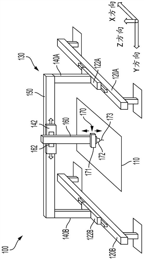
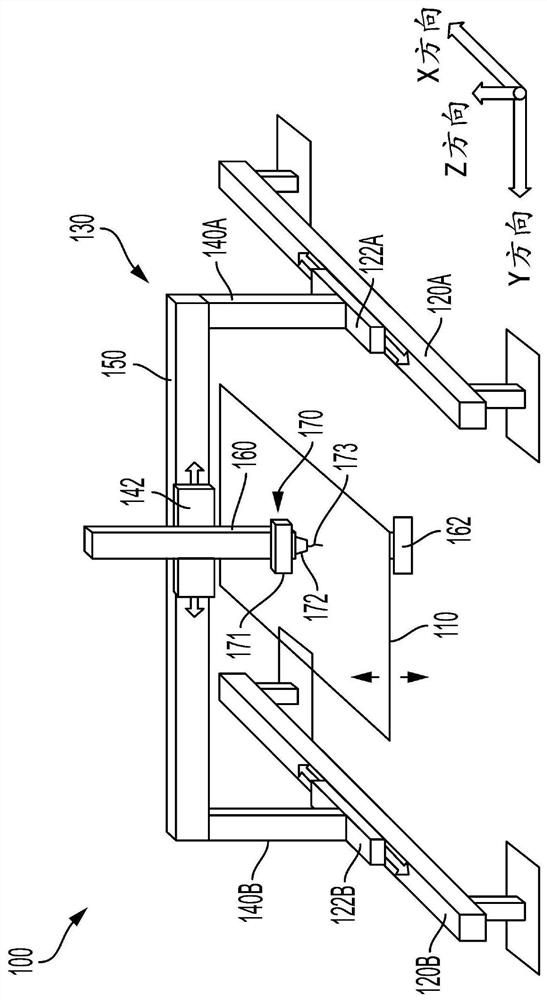
[0014] figure 1 A perspective view of a 3D printer 100 according to one embodiment is shown. As described below, printer 100 may be configured to move in three dimensions to print 3D objects on substrate 110 . Printer 100 may include one or more tracks (two shown: 120A, 120B). The rails 120A, 120B may be substantially parallel and extend along the X-axis.

[0015] The printer 100 may also include a frame 130 . The frame 130 may be coupled to the rails 120A, 120B and configured to move relative to the rails 120A, 120B. Frame 130 may include one or more legs (two legs shown: 140A, 140B). The legs 140A, 140B may be coupled to the rails 120A, 120B and configured to move relative to the rail...


PUM


Abstract

The invention discloses a three-dimensional (3D) printer. The 3D printer includes a tool configured to extrude a material onto a surface to produce a 3D object. The printer also includes a first movement device configured to move the tool in a first direction. The printer also includes a first sensor configured to measure a first electrical parameter of the first movement device as the first movement device moves the tool in the first direction. A distance between the tool and the surface is varied in response to a comparison of the first electrical parameter and a first electrical parameter threshold of the first movement device.

Description

technical field [0001] The present teachings relate generally to three-dimensional (3D) printing, and more specifically, to systems and methods for calibrating fused deposition modeling (FDM) 3D printers. Background technique [0002] There is a gap (also called standoff) between the extrusion nozzle of an FDM 3D printer and the surface it is printing on. If the gap is too small, material extruded from the nozzle may be restricted from exiting the nozzle at the desired rate due to contact with the surface, which may result in less than desired amount of material being deposited on the surface. Furthermore, if the gap is too small, the nozzle may push away previously deposited material portions (eg, underlying layers). If the gap is too large, the material may not adhere to the surface. Furthermore, if the gap is too large, the material may have poor layer-to-layer adhesion. Therefore, it is necessary to keep the gap within a predetermined range. Contents of the inventio...

Claims


Application Information

Patent Timeline
IPC IPC(8): B29C64/118B29C64/20B29C64/386B33Y10/00B33Y30/00B33Y50/00
CPCB29C64/118B29C64/20B29C64/386B33Y10/00B33Y30/00B33Y50/00B29C64/393B29C64/232B29C64/236B33Y50/02B29C64/209B29C64/227B29C64/245
Inventor C·D·布莱尔
Owner XEROX CORP
Features
  • R&D
  • Intellectual Property
  • Life Sciences
  • Materials
  • Tech Scout
  • Unparalleled Data Quality
  • Higher Quality Content
  • 60% Fewer Hallucinations
Learn More