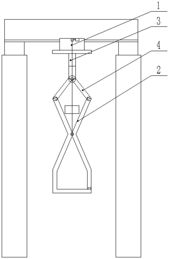
Aluminum coil self-locking safety lifting hook system

A safety hook and self-locking technology, applied in the direction of load hanging elements, trolley cranes, cranes, etc., can solve the problems of metal coils falling, and achieve the effect of increasing safety.

Pending Publication Date: 2021-03-30
安徽坤源铝业有限公司
0 Cites 0 Cited by

AI-Extracted Technical Summary

Problems solved by technology

Once the locking device of the hook loses power, it is easy ...

Abstract

The invention discloses an aluminum coil self-locking safety lifting hook system, relates to the technical field of lifting equipment, and aims to solve the problem of safety lifting. The aluminum coil self-locking safety lifting hook system comprises vertical frames arranged on the ground, longitudinal beams arranged at the tops of the vertical frames and parallel to the horizontal plane, cross beams arranged at the tops of the vertical frames and parallel to the horizontal plane, movable cranes arranged on the cross beams, two lifting arms arranged at the lower ends of the movable cranes, lifting ropes connected with the lifting arms and the movable cranes, telescopic rods arranged at the lower ends of the movable cranes, and two connecting rods arranged at the lower ends of the telescopic rods. The locking performance of the two lifting arms is guaranteed through the self-locking performance of the telescopic rods, the locking performance of the two lifting arms is further enhancedthrough pressing blocks under the condition that external energy is lost, the locking performance of the two lifting arms is guaranteed through the structure, and then the safety of the lifting hook system is improved.

Application Domain

Trolley cranesLoad-engaging elements

Technology Topic

External energyLifting equipment +1

Image

  • Aluminum coil self-locking safety lifting hook system

Examples

  • Experimental program(1)

Example Embodiment

[0013]In order to make the invention, the technical solutions and advantages will be more clearly understood, and in connection with the specific embodiments, the invention will be described in detail with reference to the accompanying drawings.
[0014]It should be noted that all expressions using "first" and "second" in the invention are in order to distinguish between two identical names of different entities or non-identical parameters, visible "first" "second" only In order to express the convenience, it is not understood that the direction and position terminology mentioned in the inventive embodiment, such as "upper", "in", "", "," ",", " "," Right "," Inner "," Outside "," Side ", etc., only refer to the direction and position of the additional pattern, so the direction and location terms used are used to illustrate and understand the invention, rather than This will not be described in this regardless of the subsequent embodiment of the present invention.
[0015]As shown, a aluminum roll self-locking safety hook system is provided based on the above object, the aluminum roll self-locking safety hook system includes a vertical frame disposed on the ground, disposed on top of the vertical frame and the horizontal plane. The stringers are disposed on the top of the vertical frame and the horizontal plane parallel, and the moving crane 1 disposed on the beam 1, two boom 2 disposed at the lower end of the moving crane 1, the hanging arm 2 and the hanging rope 1 of the moving crane 1, The telescopic rod 3 and two of the lower ends of the moving crane 1 are disposed at the lower end of the telescoping rod 3; the beam is reciprocated in the longitudinal beam, and the beam is vertical, the beam is vertical. The moving crane 1 reciprocates in the longitudinal direction of the beam.
[0016]In order to install the balance, the two of the hanging arms 2 are mirrored to each other, the symmetrical mirror surface is perpendicular to the horizontal plane, and the hanging arm 2 is divided into two sections of the left side, the upper end is ">"Shape, the lower end is" L "shape. Two of the hanging arm 2 in the upper end">>"The shape of the shape is attached to the pin hinge. The lower end of the two connecting rods 4 is hinged with the upper end end of the two cells 2; the upper end of the two connecting rods 4 is hinged with the lower end of the telescoping rod 3. The length of the connecting rod 4 is greater than the width of the hanging arm 2. The height of the thick arm 2 is controlled by the winding and release of the hanging rope, and the movement of the connecting rod 3 is driven by the telescopic rod 4. The rotation of the boom 2 is controlled. The two ends of the hanging rope are connected to the axial attachment of the moving crane 1 and the cells 2, respectively.
[0017]In order to increase and landing the boom 2, the moving crane 1 is provided with a hoisting machine, and the upper end of the hanging rope is disposed on the hoisting machine.
[0018]In order to ensure the force at the time of telescopic stretch, the telescopic rod 3 can be controlled at any time, the telescopic rod 3 is a hydraulic telescopic rod. In order to make it possible to maintain a locking state when the telescopic rod 3 is faded, the lower end of the telescoping rod 3 also hangs a block. The weight of the block is greater than 5,000 grams. The block down pull so that the connecting rod 4 maintains the pressure on the upper end of the boom 2, thereby causing the lower end of the boom 2 to remain inward, so that the boom 2 remains locked.
[0019]In order to ensure the intensity of the distressed, the vertical frame is four, the vertical plane is perpendicular to the horizontal surface, and the number of the stringers is two, and both ends of the vertical beam are fixed with a vertical top. Connecting, two of the strips are parallel to each other; each end of the beam is provided with a mobile truck, the mobile trolley is disposed at the top of the casing, and the bottom of the beam is provided with a track, the mobile crane 1 The top is hung on the track.
[0020]In order to allow the mobile crane 1 to be safely hanging, the track is inverted T-shaped. The top of the moving crane 1 is provided with a rail groove that is mounted with the track, and a drive unit is also provided on the moving crane 1, and the drive unit drives the moving crane 1 to move on the track. The drive unit includes a drive motor and a drive wheel disposed on the drive motor, the drive wheel contacts the bottom of the beam.
[0021]In order to further enhance safety, the end of the lower end of the hanging arm 2 is provided with an upward projection.
[0022]One of ordinary skill in the art will appreciate that the discussion of any of the above embodiments is merely exemplary, and is not intended to impose that the scope of the present disclosure (including the claims) is limited to these examples; in the idea of ​​the invention, the above embodiments or different The technical features in the examples may also be combined, and the steps can be implemented in any order, and there are many other changes in the different aspects of the invention described above, and they are not provided in detail.
[0023]Although the invention has been described in conjunction with the specific embodiments of the invention, many replacements, modifications, and variations of these embodiments will be apparent to those of ordinary skill in the art.
[0024]Embodiments of the invention are intended to cover all such alternatives, modifications, and variations that fall within the broad range of the appended claims. Therefore, any other omitted, modified, equivalent replacement, improvement, etc., etc., etc., should be included within the scope of the invention.

PUM

no PUM

Description & Claims & Application Information

We can also present the details of the Description, Claims and Application information to help users get a comprehensive understanding of the technical details of the patent, such as background art, summary of invention, brief description of drawings, description of embodiments, and other original content. On the other hand, users can also determine the specific scope of protection of the technology through the list of claims; as well as understand the changes in the life cycle of the technology with the presentation of the patent timeline. Login to view more.

Similar technology patents

Trusted computing platform chip applicable to mobile communication equipment and authentication method thereof

InactiveCN101986641Aimprove securityachieve security
Owner:HANGZHOU SYNOCHIP DATA SECURITY TECH CO LTD

Malicious website prompt method and router

ActiveCN104125209Aimprove security
Owner:TENCENT TECH (SHENZHEN) CO LTD +1

Hidden frame glass curtain wall structure and method for mounting same

InactiveCN107829513AImprove decorationimprove security
Owner:XINCHANG SICHUANG DESIGN CONSULTING CO LTD

Intelligent door lock identity authentication method and system, readable storage medium and mobile terminal

ActiveCN109712278APrevent Identity Leakageimprove security
Owner:深圳市小石安防科技有限公司

Classification and recommendation of technical efficacy words

Why Eureka
Try Eureka