Clutch, clutch transmission system and clothes treatment equipment
A technology of clutches and clutch sleeves, which is applied in the field of clutches, can solve problems such as the large movement stroke of the shift fork, affect the use effect, and unfavorable compact design of product parts, and achieve the effect of facilitating compact design, reducing the amount of space, and reducing the amount of movement stroke
- Summary
- Abstract
- Description
- Claims
- Application Information
AI Technical Summary
Problems solved by technology
Method used
Image
Examples
Embodiment 1
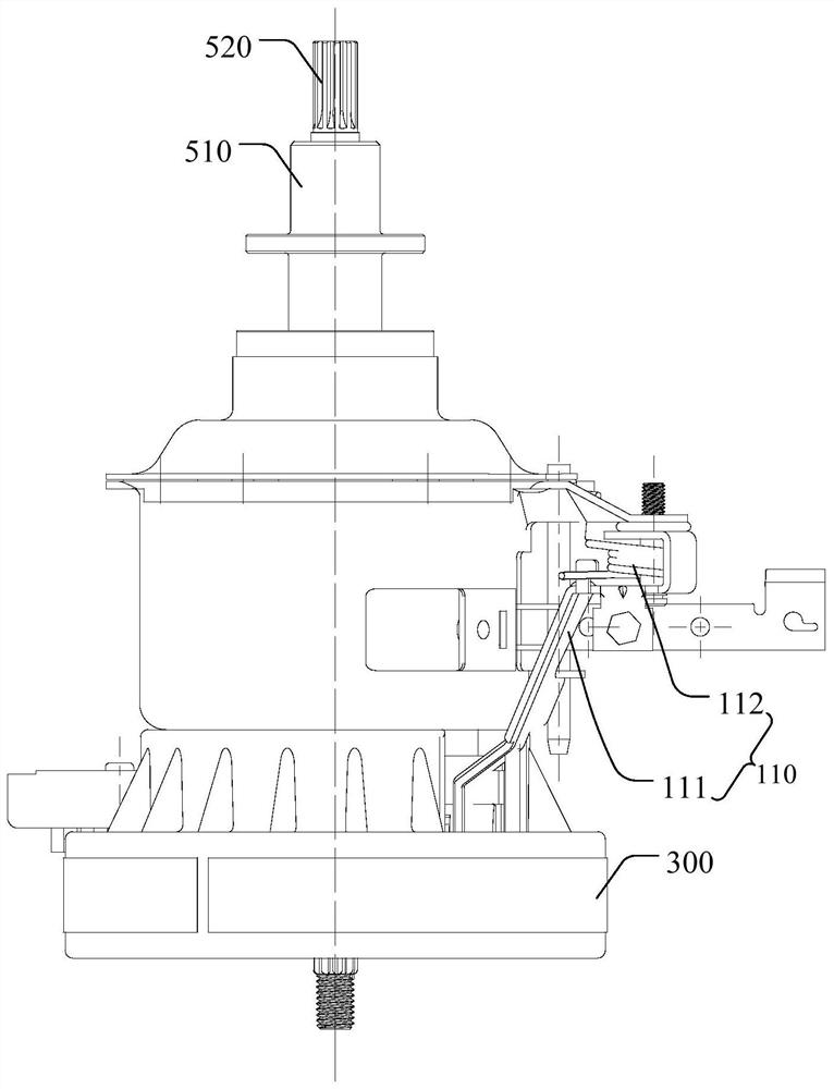
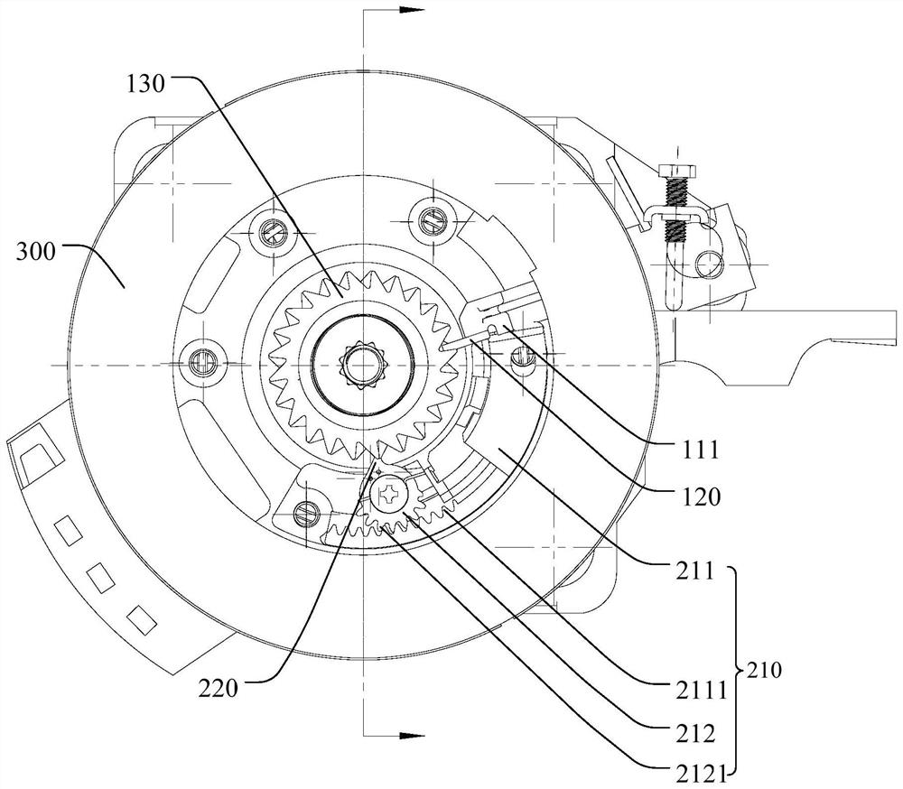
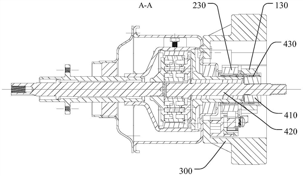
[0049] Such as figure 1 and figure 2 As shown, the clutch provided in this embodiment includes: a first shift fork 110 , a first ratchet 130 , a second shift fork 210 and a second ratchet 230 .
[0050] Specifically, the first shift fork 110 is provided with a first ratchet 120, and the first shift fork 110 is configured to drive the first ratchet 120 so that the first ratchet 120 is engaged or separated from the first ratchet 130; the second shift fork 210 A second ratchet 220 is provided, and the second shift fork 210 is configured to drive the second ratchet 220 so that the second ratchet 220 engages with or separates from the second ratchet 230 .
[0051] In the clutch provided by the above-mentioned embodiments of the present invention, the first shift fork 110 and the second shift fork 210 are provided to respectively drive the first ratchet 120 and the second ratchet 220 to form double ratchets. The structural form makes the engagement and separation of the first rat...
Embodiment 2
[0053] Such as figure 2 and Figure 6 As shown, in addition to the features of the above-mentioned embodiments, this embodiment further defines: the second shift fork 210 includes a linkage mechanism (for details, please refer to the attached Figure 6 The slider 211, the movable part 212, the first elastic member 214, etc.), the linkage mechanism is transmitted between the first shift fork 110 / first ratchet 120 and the second ratchet 220, and when the first shift fork 110 drives The first pawl 120 moves to a position separated from the first ratchet 130, and the first shift fork 110 / first pawl 120 triggers the linkage mechanism to link the second pawl 220, so that the second pawl 220 is separated from the second ratchet 230 positional movement.
[0054] It is worth noting that linkage, as the name suggests, can be understood as a number of related things. When one moves or changes, the others also move or change. This solution can be understood as that the first shift for...
Embodiment 3
[0059] Such as figure 2 As shown, in addition to the features of the above-mentioned embodiment 2, this embodiment further defines: the linkage mechanism includes a slider 211 and a movable member 212 .
[0060] Specifically, the slider 211 is provided with a first engaging part 2111; the movable part 212 is provided with a second engaging part 2121 and the second engaging part 2121 is engaged with the first engaging part 2111 for transmission, and the second pawl 220 is arranged on the movable part. 212, the first shift fork 110 / first ratchet 120 abuts against the slider 211 and drives the slider 211 to slide, so that the slider 211 drives the second ratchet 220 to the position of engaging with the second ratchet 230 via the movable part 212 sports. Among them, the meshing transmission has the advantages of good transmission stability and high transmission precision, which can help to improve the movement accuracy of the second pawl 220 and the consistency with the action o...
PUM
 Abstract
Description
Claims
Application Information
 - R&D
- Intellectual Property
- Life Sciences
- Materials
- Tech Scout
- Unparalleled Data Quality
- Higher Quality Content
- 60% Fewer Hallucinations
Browse by: Latest US Patents, China's latest patents, Technical Efficacy Thesaurus, Application Domain, Technology Topic, Popular Technical Reports.
© 2025 PatSnap. All rights reserved.Legal|Privacy policy|Modern Slavery Act Transparency Statement|Sitemap|About US| Contact US: help@patsnap.com


