Composite spray bars

A technology of seamless lumens and components, applied in the direction of injection devices, injection devices, jet propulsion devices, etc., can solve the problems of impractical maintenance components, no optimization, difficult production, etc., to reduce weight, prolong life, and reduce costs Effect

Pending Publication Date: 2021-07-23
WOODWARD GOVERNOR CO
View PDF0 Cites 0 Cited by
  • Summary
  • Abstract
  • Description
  • Claims
  • Application Information

AI Technical Summary

Problems solved by technology

[0005] Existing methods for manufacturing fuel manifolds required the assembly of dozens of individually machined components and resulted in a large number of joints within the assembly
Such components can be very complex and difficult to produce, and therefore can be very expensive
Such assemblies may not be optimized for fuel flow and may require extensive external stays for support and reinforcement
Beyond that, it may be impractical to repair the final assembly

Method used


Image

  • Composite spray bars
  • Composite spray bars
  • Composite spray bars

Examples


Embodiment Construction

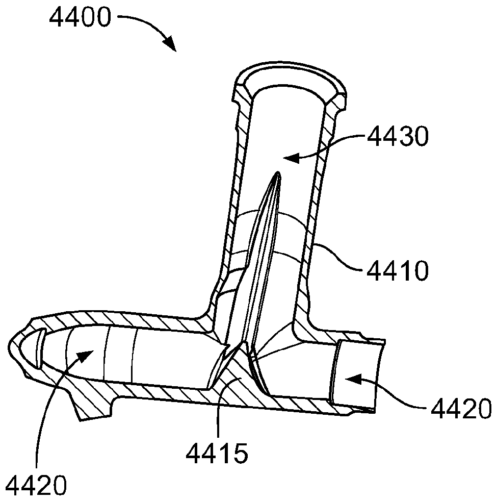
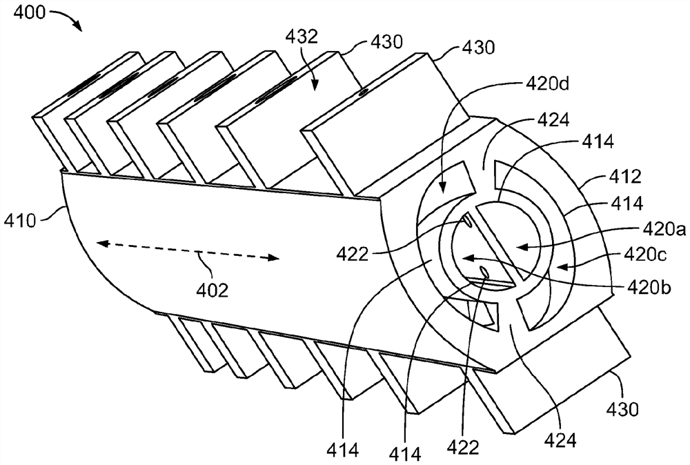
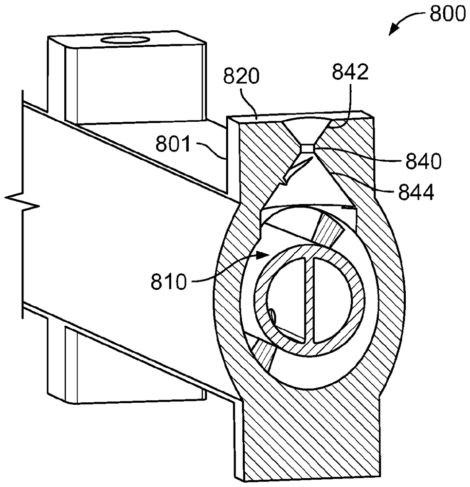
[0093] This specification describes systems and techniques for fabricating fluid (eg, fuel) delivery components with integral lumens (eg, fluid channels). In general, jet engine fuel booms, jet engine fuel manifolds, and other types of fluid delivery components can have complex designs with complex combinations and arrangements of fluid passages, supports, inlets, outlets, mounting features, and other features .

[0094] Traditional manufacturing techniques such as machining, molding, and extrusion suffer from their ability to form parts with complex 3D geometries, especially those with complex internal geometries (e.g., lumens, cavities, discontinuities). limit. As such, complex devices have traditionally consisted of a large number of individually fabricated, simpler subcomponents that are welded or brazed together to form complex assemblies. Some examples of conventional fuel manifolds manufactured using conventional techniques include nearly a hundred individual machined...


PUM


Abstract

The subject matter of the specification can be embodied in, among other things, a fuel delivery component, including a substantially rigid, unitary structure formed as a single piece of material, and at least a first seamless lumen defined by the unitary structure.

Description

[0001] priority claim [0002] This application claims priority to U.S. Provisional Patent Application No. 62 / 736,367, filed September 25, 2018, and U.S. Patent Application No. 16 / 352,290, filed March 13, 2019, the entire contents of which applications are incorporated by reference into This article. technical field [0003] This specification relates to multi-lumen fuel distribution components. Background technique [0004] Gas turbine engines can have complex assemblies of manifold tubes and machined components that deliver fuel to spray bars or fuel nozzles that inject fuel into the combustors. Typically, these components consist of a large number of individually machined parts that are assembled and permanently joined together by welding or brazing. An example of this is the manifold subassembly of the afterburner of a turbofan jet engine. [0005] Existing methods for manufacturing fuel manifolds require the assembly of dozens of individually machined components and ...

Claims


Application Information

Patent Timeline
Patent Type & Authority Applications(China)
IPC IPC(8): F02C7/22F02K3/10F23R3/20B33Y10/00B33Y80/00
CPCB22F7/08B33Y10/00B33Y80/00F02C7/222F02K3/10F05D2230/31F05D2250/25F23R3/20B05B1/205F05D2220/323F05D2230/30B05B1/02B05B1/14B05B1/20F16L9/20F16L9/19
Inventor M·A·布鲁姆S·E·拉坦M·G·格德克
Owner WOODWARD GOVERNOR CO
Why Eureka
Try Eureka