
Method and device for transmitting UCI, terminal and base station

A transmission method and terminal technology, applied in the wireless field

Pending Publication Date: 2021-03-30
DATANG MOBILE COMM EQUIP CO LTD
View PDF5 Cites 3 Cited by
  • Summary
  • Abstract
  • Description
  • Claims
  • Application Information

AI Technical Summary

Problems solved by technology

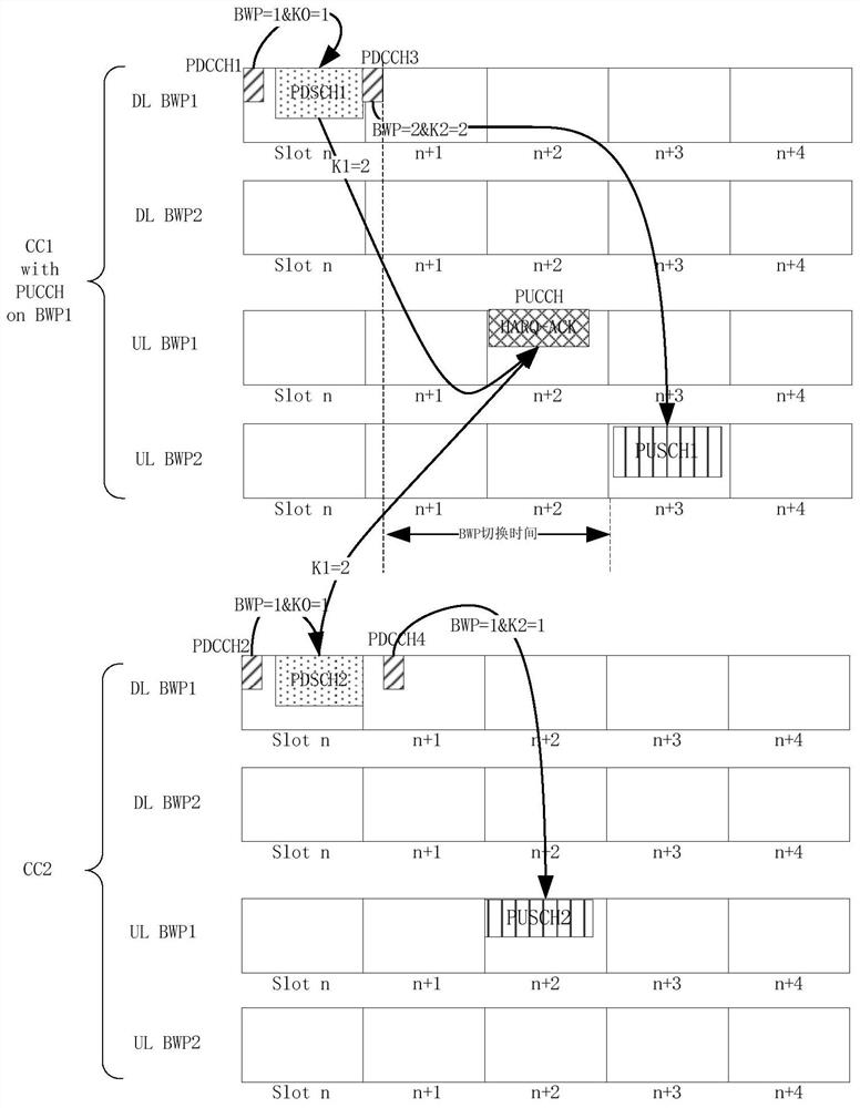
[0006] The purpose of the present invention is to provide a transmission method, device, terminal and base station for uplink control information UCI, which is used to solve the problem that when BWP switching occurs, if the transmission time of the PUCCH carrying UCI is within the BWP switching time and overlaps with the PUCCH UCI transmission problem during PUSCH

Method used


Image

  • Method and device for transmitting UCI, terminal and base station
  • Method and device for transmitting UCI, terminal and base station
  • Method and device for transmitting UCI, terminal and base station

Examples


Embodiment Construction

[0137] In order to make the technical problems, technical solutions and advantages to be solved by the present invention clearer, the following will describe in detail with reference to the drawings and specific embodiments.

[0138] The UCI transmission method, terminal and base station described in the embodiments of the present invention can be applied in a wireless communication system. The wireless communication system may be a 5G system, or an evolved long term evolution (Evolved Long Term Evolution, eLTE) system, or a subsequent evolution communication system. refer to figure 1 , which provides a schematic structural diagram of a wireless communication system to which the transmission method is applied in an embodiment of the present invention. Such as figure 1 As shown, the wireless communication system may include: a base station 10 and a terminal 11 , and the terminal 11 may be connected to the base station 10 . In practical applications, the connection between th...


PUM


Abstract

The invention provides a method and a device for transmitting uplink control information (UCI), a terminal and a base station. The transmission method comprises the following steps: when the transmission moment of a PUCCH bearing UCI is within the BWP switching time of a carrier where the PUCCH is transmitted and a PUSCH overlapped with the PUCCH exists, adopting one of the following transmissionmodes: discarding the UCI; and discarding the PUCCH, and transmitting the UCI on the PUSCH. By adopting the method, for the scene that the transmission moment of the PUCCH bearing the UCI is within the BWP switching time of the carrier where the PUCCH is transmitted and the PUSCH overlapped with the PUCCH exists, one processing mode of directly discarding the UCI, discarding the PUCCH and transferring the UCI to the PUSCH for transmission can be adopted to definitely stipulate the UCI transmission method in the scene, and consistent understanding of UCI transmission behaviors by the terminal and the base station is ensured.

Description

technical field [0001] The present invention relates to the field of wireless technologies, in particular to a UCI transmission method, device, terminal and base station. Background technique [0002] In the 5G NR system, a carrier can contain up to 4 bandwidth parts (BandWidth Part, BWP). At present, the terminal will only work on one BWP at a time, and this BWP is called the active BWP. [0003] The activation of the BWP can be triggered by a timer, or by scheduling the Physical Downlink Control Channel (PDCCH) of the Physical Downlink Shared Channel (PDSCH) or the Physical Uplink Shared Channel (PUSCH) Dynamically indicate BWP switching, that is, the DCI used by PDCCH contains the BWP indication field, indicating which BWP on the scheduled carrier the terminal receives PDSCH or sends PUSCH, and the indicated BWP is the active BWP. When the indicated BWP number is different from When receiving the BWP number of PDSCH or sending PUSCH before, it indicates that the terminal...

Claims


Application Information

Patent Timeline
IPC IPC(8): H04W72/04H04L5/00
CPCH04L5/0053H04W72/20H04W72/04H04L5/00
Inventor 高雪娟
Owner DATANG MOBILE COMM EQUIP CO LTD
Learn More