Smooth cable paying-off device

A pay-off device and cable technology, which is used in transportation and packaging, delivery of filamentous materials, thin material processing, etc., can solve problems such as cable rotation, cable shaft position cannot be adjusted at will, and large labor force to ensure stability The effect of rotation

Inactive Publication Date: 2021-04-02
哈尔滨金玉钰科技开发有限公司
View PDF0 Cites 0 Cited by
  • Summary
  • Abstract
  • Description
  • Claims
  • Application Information

AI Technical Summary

Problems solved by technology

[0002] In the process of paying out the cable shaft, it is often paid out by manpower, which requires a lot of labor. Although there are pay-off devices that use machinery instead of manual work in the prior art, the pay-out speed is too fast during the pay-out process, which is easy The phenomenon that the cables are piled up and rotated on the cable shaft, and the position of the cable shaft cannot be adjusted arbitrarily, which can no longer meet the actual use needs

Method used


Image

  • Smooth cable paying-off device
  • Smooth cable paying-off device
  • Smooth cable paying-off device

Examples


specific Embodiment approach 1

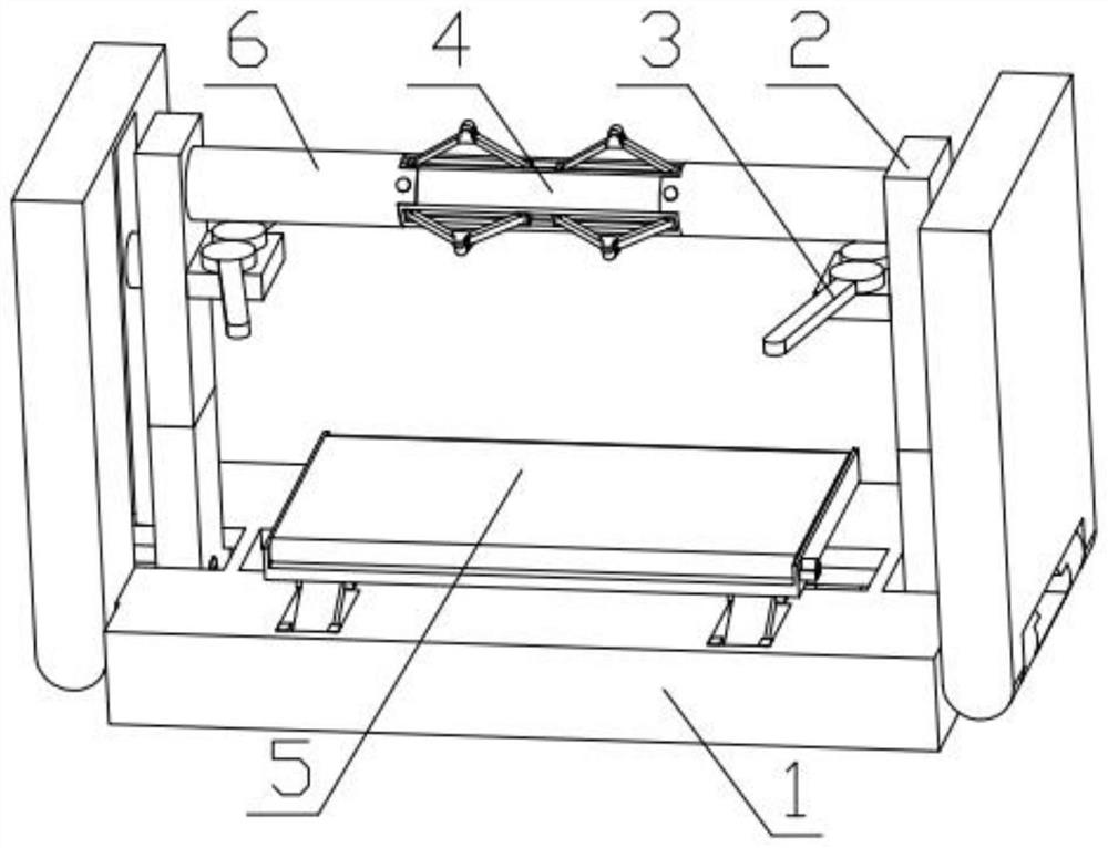
[0036] Combine below Figure 1-15 Describe this embodiment, a cable smooth pay-off device, including a folding base 1, a lifting mechanism 2, a position adjustment mechanism 3, a cable shaft positioning mechanism 4, a wire-releasing anti-jamming mechanism 5 and a connecting mechanism 6, the folding base 1 An anti-jamming mechanism 5 is fixedly installed on the top, and a lifting mechanism 2 is slidably installed in the groove of the folding base 1. A position adjustment mechanism 3 is fixedly installed on the lifting mechanism 2. In the groove, the cable shaft positioning mechanism 4 is slidably installed on the lifting mechanism 2 .

specific Embodiment approach 2

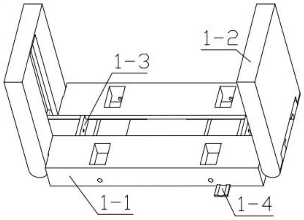
[0038] Combine below Figure 1-15 This embodiment will be described. This embodiment will further explain Embodiment 1. The folding base 1 includes a main base plate 1-1, a side slideway plate 1-2, a positioning plate 1-3, and a motor fixing plate 1-4. The two ends of the base plate 1-1 are respectively hinged with side slideway plates 1-2, the two sides of the main base plate 1-1 are fixedly installed with a positioning plate 1-3, and the main base plate 1-1 is fixedly installed with a motor fixing plate 1-4 .

specific Embodiment approach 3

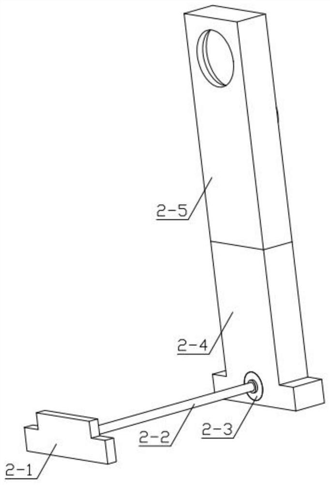
[0040] Combine below Figure 1-15 Describe this embodiment, this embodiment will further explain the second embodiment, the lifting mechanism 2 includes a limit slider 2-1, a displacement threaded rod 2-2, a displacement motor 2-3, a sliding base 2-4, Upper connecting piece 2-5, shaft rotating motor 2-6, gear for rotation 2-7, limit rod 2-8, hydraulic rod 2-9, limit slider 2-1 is slidably installed on the main base plate 1-1 In the groove provided above, one end of the displacement threaded rod 2-2 is rotated and installed in the groove provided on the limit slider 2-1, and the other end of the displacement threaded rod 2-2 is fixedly mounted on the displacement motor 2-3. At the output end, the displacement motor 2-3 is fixedly installed in the groove provided on the sliding base 2-4, and the sliding base 2-4 is slidably installed in the groove provided on the main base plate 1-1, and the concave groove of the sliding base 2-4 The hydraulic rod 2-9 is fixedly installed in th...


PUM


Abstract

The invention relates to a cable related device, in particular to a smooth cable paying-off device. The device comprises a folding base, a lifting mechanism, a position adjusting mechanism, a cable shaft positioning mechanism, a paying-off anti-clamping mechanism and a connecting mechanism; the paying-off anti-clamping mechanism is fixedly installed on the folding base; the lifting mechanism is glidingly installed in a groove of the folding base; the position adjusting mechanism is fixedly installed on the lifting mechanism; the connecting mechanism is rotationally installed in a groove formedin the lifting mechanism; and the cable shaft positioning mechanism is glidingly installed on the lifting mechanism. The device can adapt to cable shafts with different diameters and different widths, the device can adjust the positions of the cable shafts in the paying-off process and cooperate with cable paying-off to achieve the smooth purpose, the device has the function of assisting cable paying-off, and it is guaranteed that cables cannot be accumulated.

Description

technical field [0001] The invention relates to a cable-related device, in particular to a cable fluent pay-off device. Background technique [0002] In the process of paying out the cable shaft, it is often paid out by manpower, which requires a lot of labor. Although there are pay-off devices that use machinery instead of manual work in the prior art, the pay-out speed is too fast during the pay-out process, which is easy The phenomenon that the cables are piled up and rotated on the cable shaft is caused, and the position of the cable shaft cannot be adjusted arbitrarily, which cannot meet the actual use requirements. Contents of the invention [0003] The main technical problem to be solved by the present invention is to provide a smooth cable pay-off device. The device can adapt to cable shafts of different diameters and widths. The device can adjust the position of the cable shaft during the pay-off process and cooperate with the cable pay-off to achieve For the pur...

Claims


Application Information

Patent Timeline
IPC IPC(8): B65H49/36B65H49/20B65H49/32B65H49/34B65H59/04
CPCB65H49/20B65H49/32B65H49/321B65H49/34B65H49/36B65H59/04B65H2701/34
Inventor 化国栋
Owner 哈尔滨金玉钰科技开发有限公司
Why Eureka
Try Eureka